
Passive intelligent lock cylinder and passive intelligent padlock

A technology of smart locks and padlocks, applied in the field of locks, can solve the problems of high production cost and complexity

Pending Publication Date: 2020-10-20
穆武龙
View PDF0 Cites 1 Cited by
  • Summary
  • Abstract
  • Description
  • Claims
  • Application Information

AI Technical Summary

Problems solved by technology

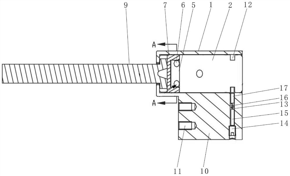
[0005] For this reason, based on the defects in the above-mentioned prior art, the purpose of the present invention is to propose a passive intelligent lock cylinder and a passive intelligent padlock, both of which can realize the idling of the lock cylinder body in the non-open state, and can Effectively prevent violent damage to the lock cylinder when the lock cannot be unlocked, avoid abnormal opening and closing of the lock, and effectively improve the safety and anti-destructive properties of the lock; at the same time, both locks adopt a new steel ball clutch structure , which effectively solves the defects of complex structural design and high production cost of traditional locks

Method used


Image

  • Passive intelligent lock cylinder and passive intelligent padlock
  • Passive intelligent lock cylinder and passive intelligent padlock
  • Passive intelligent lock cylinder and passive intelligent padlock

Examples


Embodiment

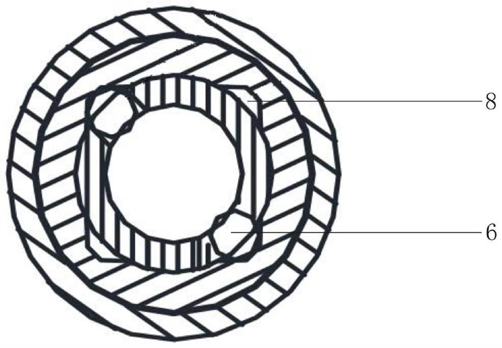
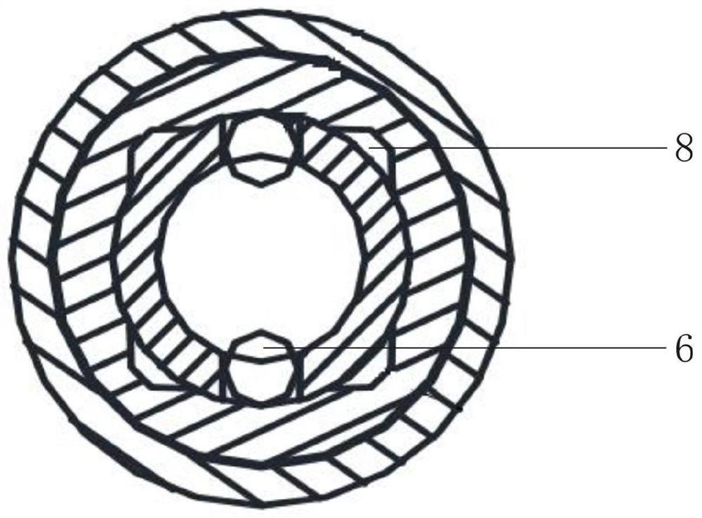
[0043] Such as Figure 1-4 As shown, the embodiment of the present invention discloses a passive intelligent lock cylinder, including a lock case 1 , a lock cylinder body 2 and a key 3 .

[0044] The lock housing 1 is fixed on the panel of the door lock. Specifically, a fixed block 10 is integrally arranged outside the housing of the lock housing 1. The axial direction of the fixed block 10 is parallel to the axial direction of the lock housing 1. The fixed block 10 Two screw holes are provided on the side close to the lock cylinder plectrum 9, and the lock housing 1 is fixed to the panel of the fixed door lock through the two screw holes and the correspondingly tightened two screws 11.

[0045] The lock core body 2 is placed inside the lock case 1 and is rotatably connected with the inner wall of the lock case 1. Specifically, a circle of first grooves 12 is arranged on the periphery of the lock core body 2 along its circumferential direction, and a ring of first grooves 12 i...


PUM


Abstract

The invention discloses a passive intelligent lock cylinder and a passive intelligent padlock. The passive intelligent lock cylinder comprises a lock shell, a lock cylinder body, a key, a driver, a steel ball, a clutch, a semicircular groove, a lock cylinder shifting piece and the like, after the key supplies power to the driver in the lock cylinder body, the driver can eject the steel ball out, so that the steel ball is exactly clamped into the semicircular groove in the inner wall of the clutch, at the moment, the key is rotated again to drive the lock cylinder shifting piece outside the clutch to rotate, and the unlocking process is achieved. The passive intelligent padlock comprises a lock beam, a lock shell, a lock cylinder body, a key, a driver shifting block, steel balls, a transverse channel, a semicircular groove and the like, after the key supplies power to the driver shifting block in the lock cylinder body, the driver shifting block horizontally pushes out the steel balls on the two sides, the steel balls are exactly clamped into the semicircular groove of a U-shaped clamping section of the lock beam, and the padlock locking process is achieved. According to the passiveintelligent lock cylinder and the passive intelligent padlock, the structural design is simple, the manufacturing cost is low, and an idling structure is adopted to overcome the defect that a lock isabnormally opened and closed due to violent damage to a lock cylinder body.

Description

technical field [0001] The invention relates to the technical field of locks, more specifically, to a passive intelligent lock cylinder and a passive intelligent padlock. Background technique [0002] With the continuous development of modern science and technology, technological products have been widely used in our lives. In the field of locks, smart locks have become a new type of locks for household use, which can provide better security without The source smart lock is a kind of lock with high intelligence, security and quickness. [0003] The existing passive smart locks generally adopt the design idea of ​​combining the blade marble structure and the mechanical clutch structure, which makes the internal structure relatively complicated and the production cost is high, and the existing passive smart lock still has the problem that the lock cylinder cannot idling, there is no way to prevent it from being destroyed by violence. [0004] Therefore, how to optimize the s...

Claims


Application Information

Patent Timeline
IPC IPC(8): E05B47/06E05B67/24E05B67/18E05B19/00E05B17/10E05B67/38
CPCE05B17/103E05B19/00E05B47/0002E05B47/0653E05B67/18E05B67/24E05B67/38E05B2047/0026E05B2047/0063
Inventor 穆武龙
Owner 穆武龙
Learn More