
Concrete crack picture splicing and detecting method

A detection method and concrete technology, applied in the field of detection and stitching of concrete crack pictures, can solve the problems of single picture, failure to achieve large-scale crack picture stitching, integration of detection, and inability to obtain the complete shape and relative position of cracks.

Active Publication Date: 2020-10-20
UNIV OF SHANGHAI FOR SCI & TECH +1
View PDF7 Cites 0 Cited by
  • Summary
  • Abstract
  • Description
  • Claims
  • Application Information

AI Technical Summary

Problems solved by technology

In practical engineering applications, the existing crack detection methods based on image processing have many deficiencies, which are mainly reflected in two aspects: first, the detection object is a single picture, and the splicing and detection integration of large-scale crack pictures has not been realized, so it is impossible to Obtain the complete shape and relative position of the crack
Although there are some splicing methods for planar images, they are not suitable for large-scale image splicing because the images are rotated and scaled during the splicing process, and the image information is changed during the transformation, so they are not suitable for crack parameter measurement.
Second, in order to meet the precision requirement of 0.2mm in engineering inspection, the existing method requires high image quality, so the area of ​​each inspection is small, which seriously reduces the work efficiency

Method used


Image

  • Concrete crack picture splicing and detecting method
  • Concrete crack picture splicing and detecting method
  • Concrete crack picture splicing and detecting method

Examples


Embodiment Construction

[0051] The present invention will now be further described in conjunction with the embodiments and drawings:

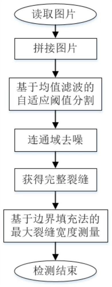
[0052] The method for splicing and detecting crack pictures provided by the embodiment of the present invention, the flowchart is as follows figure 1 As shown, the method specifically includes the following steps:

[0053] (1) Mosaic pictures;

[0054] (2) Adaptive threshold segmentation based on mean filtering;

[0055] (3) Denoising of connected domains;

[0056] (4) The maximum width measurement method based on boundary filling measures the maximum width and position of cracks.

[0057] The following is a detailed description of each step:

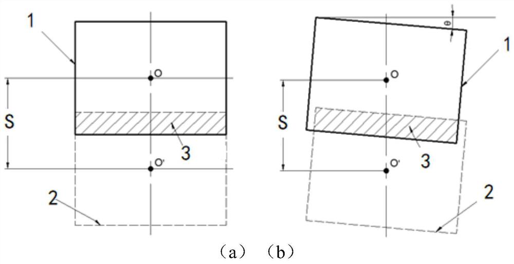
[0058] First of all, in order to facilitate the understanding of the embodiments of the present invention, a phenomenon in the camera shooting process is introduced here, such as figure 2 As shown, when the camera shoots a plane along a straight line (camera displacement S), in the ideal shooting state, see figure 2 (A), the width of th...


PUM


Abstract

The invention discloses a concrete crack picture splicing and detecting method which comprises the following steps: reading a plurality of to-be-detected original pictures; calculating the size of anoverlapping region according to a feature point matching result, and splicing the plurality of pictures; performing adaptive threshold segmentation based on mean filtering; removing noisy points according to the circularity and the shape extremum; and calculating the crack width based on a boundary filling method, and calibrating the crack maximum width. The method is high in calculation efficiency and high in detection precision, the problem of poor picture splicing effect in the prior art is solved, high-quality splicing of complete plane pictures can be achieved, then the complete form anddistribution condition of cracks can be obtained, the maximum width and corresponding positions of the cracks can be accurately calibrated, and the method is more suitable for engineering applicationenvironments.

Description

Technical field [0001] The invention relates to a computer processing method for splicing concrete crack pictures, in particular to a method for splicing and detecting concrete crack pictures. Background technique [0002] Surface cracks are one of the important indicators for concrete structure monitoring and damage identification. There are many reasons for surface cracks in concrete structures, such as temperature stress, fatigue load, material aging, and structural deformation. When the crack width is greater than 0.2mm, the concrete will fall off, carbonize, and corrode steel bars. In severe cases, collapse accidents will occur. Therefore, the identification and calibration of concrete crack indicators, especially the maximum crack width, has very important practical significance for ensuring the safety of concrete structures. [0003] At present, the commonly used crack detection method is the image processing method. After crack picture preprocessing, crack extraction, cra...

Claims


Application Information

Patent Timeline
Patent Type & Authority Applications(China)
IPC IPC(8): G06T7/00G06T7/11G06T7/136G06T7/62G06T3/40G06T5/00
CPCG06T7/0004G06T7/11G06T7/136G06T7/62G06T3/4038G06T2207/10004G06T2207/30132G06T5/70
Inventor 王艳唐财聪丁文胜吴成振
Owner UNIV OF SHANGHAI FOR SCI & TECH
Learn More