Rolling pin grinding device

A rolling pin and drive shaft technology, which can be applied to grinding machines, grinding workpiece supports, grinding/polishing equipment, etc., can solve the problems of low rolling pin efficiency and uneven grinding shape.

Active Publication Date: 2020-10-23
泰安泰悦食坊食品有限公司
View PDF10 Cites 2 Cited by
  • Summary
  • Abstract
  • Description
  • Claims
  • Application Information

AI Technical Summary

Problems solved by technology

[0005] In order to overcome the shortcomings of low efficiency and uneven grinding shape of manual grinding rolling pins, the technical problem to be solved is: to provide a rolling pin grinding device with relatively uniform grinding shape and which can be polished and cleaned at the same time

Method used


Image

  • Rolling pin grinding device
  • Rolling pin grinding device
  • Rolling pin grinding device

Examples


Embodiment 1

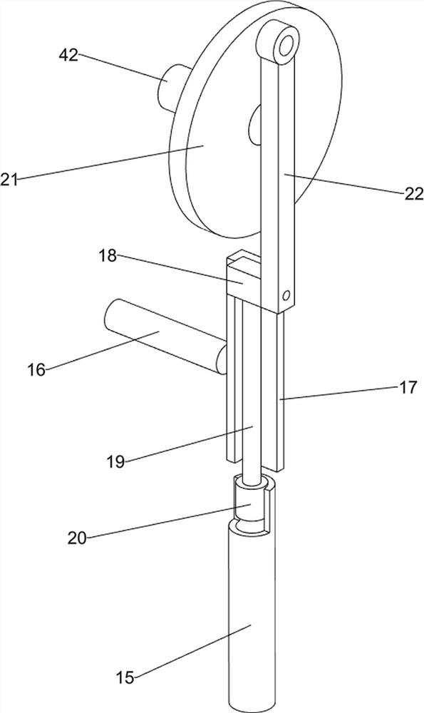
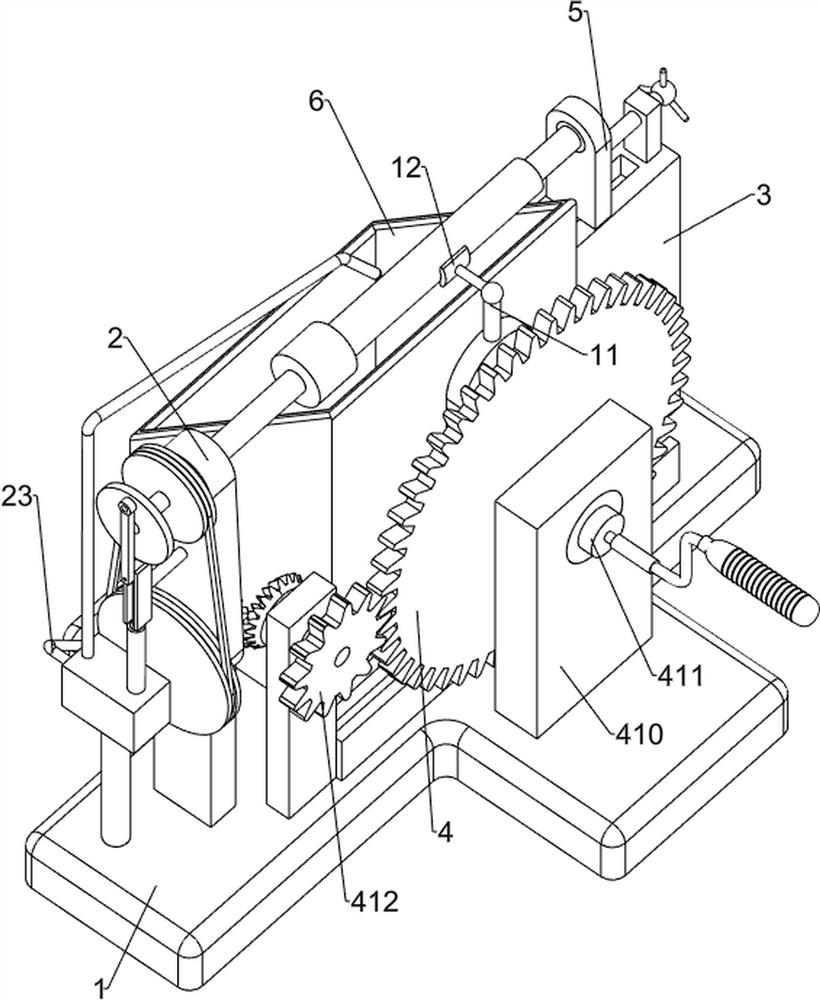
[0021] Such as Figure 1-2 As shown, a rolling pin grinding device includes a base 1, a bracket 2, a cushion block 3, a rotating mechanism 4, a clamping mechanism 5 and a water tank 6, the left side of the top of the base 1 is provided with a bracket 2, and the right side of the top of the base 1 is provided with a Block 3, a rotation mechanism 4 is provided on the top middle side of the base 1, a clamping mechanism 5 is provided on the upper end of the block 3, the clamping mechanism 5 cooperates with the rotation mechanism 4, a water tank 6 is provided on the top middle side of the base 1, and the water tank 6 Located between pad 3 and bracket 2.

[0022] When people need to polish the rolling pin, put the rolling pin between the clamping mechanism 5 and the rotating mechanism 4, the clamping mechanism 5 fixes the rolling pin, then people rotate the rotating mechanism 4, and the rotating mechanism 4 rotates to drive the rolling pin to rotate, and people can now The rolling ...

Embodiment 2

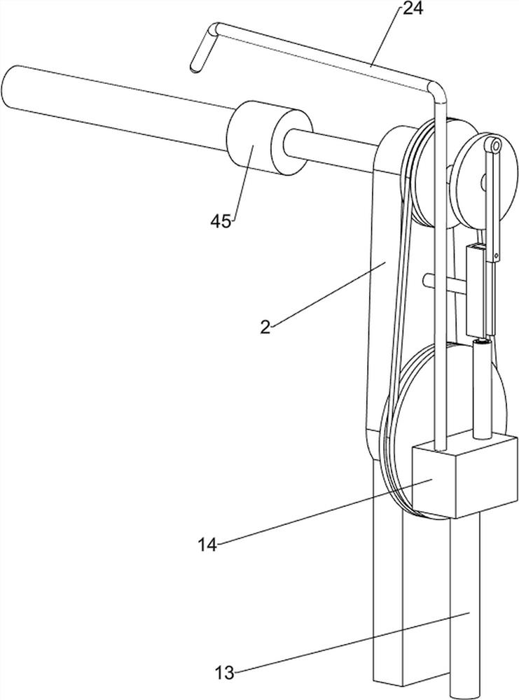
[0028] Such as Figure 3-4 As shown, on the basis of Embodiment 1, a rolling pin grinding device also includes a first slide rail 7, a second slide block 8, a return-shaped groove plate 9, a guide post 10, a first support post 11 and a friction block 12. The first slide rail 7 is set in the middle of the top of the base 1, and the second slide block 8 is set in the sliding type inside the first slide rail 7. The second slide block 8 is provided with a return-shaped groove plate 9, and the rear side wall of the large gear 413 The position is eccentrically provided with a guide post 10, the guide post 10 is slidingly matched with the return-shaped groove plate 9, the upper end of the return-shaped groove plate 9 is provided with a first support column 11, and a friction block 12 is arranged on the first support column 11.

[0029] In order to polish the rolling pin more evenly, when people turn the handle 414, the large gear 413 rotates to drive the guide post 10 to rotate, and ...


PUM


Abstract

The invention relates to a grinding device, in particular to a rolling pin grinding device. The rolling pin grinding device is uniform in grinding shape and can conduct grinding and cleaning at the same time. The rolling pin grinding device comprises a base, a cushion block, a rotating mechanism, a clamping mechanism and a water tank, wherein a support is arranged on one side of the top of the base; the cushion block is arranged on the other side of the top of the base; the rotating mechanism is arranged on one side of the middle of the top of the base; the clamping mechanism is arranged at the upper end of the cushion block and matched with the rotating mechanism; and the water tank is arranged on one side of the middle of the top of the base and located between the cushion block and thesupport. According to the rolling pin grinding device, through cooperation of the rotating mechanism and the clamping mechanism, a rolling pin is fixed and then ground, the grinding procedure is simpler, and the shape of the ground rolling pin is standard.

Description

technical field [0001] The invention relates to a grinding device, in particular to a rolling pin grinding device. Background technique [0002] The rolling pin is a very ancient tool used to press noodles in China. It has been handed down to this day. Most of the rolling pins are wooden and cylindrical. They are used to roll the dough until the dough is thinned. Therefore, the rolling pin is used to make noodles and dumplings. Indispensable tools such as wrappers, wonton wrappers and noodle cakes. [0003] At present, most of the rolling pins sold on the market are manually polished by people, and the price is relatively high. At the same time, people polish the rolling pin by hand, which is not only time-consuming and laborious, but also has the risk of grinding and hurting the hands. At the same time, the shape of the polished is not uniform enough. The grinding process also requires continuous cleaning by hand. [0004] Therefore need to research and develop a kind of ...

Claims


Application Information

Patent Timeline
Patent Type & Authority Applications(China)
IPC IPC(8): B24B5/50B24B5/04B24B5/35B24B41/06B08B3/02
CPCB24B5/50B24B5/04B24B5/35B24B41/06B08B3/02
Inventor 丁奕之
Owner 泰安泰悦食坊食品有限公司
Why Eureka
Try Eureka