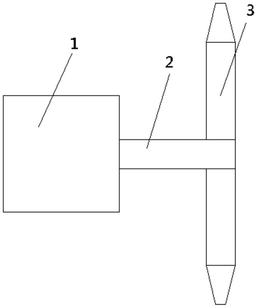
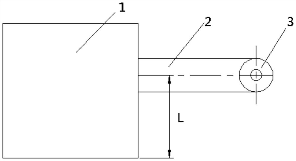
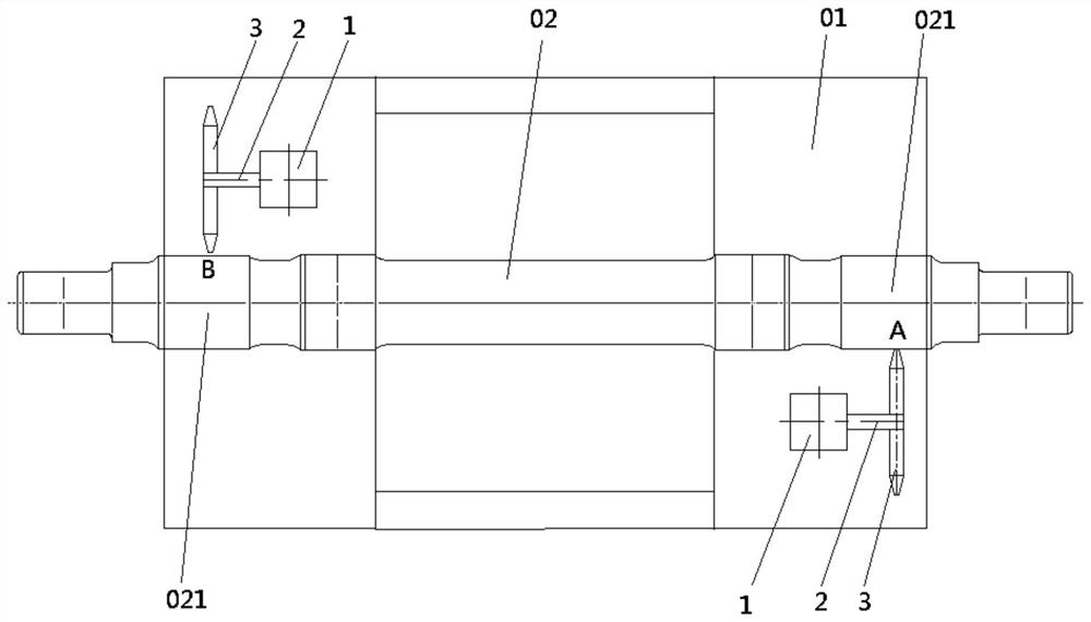
Phase marking device
A scribing device and a scribing position technology, applied to workshop equipment, manufacturing tools, etc., can solve the problems of operator use, inconvenient storage, unusable, difficult quantification of phase values, etc.
- Summary
- Abstract
- Description
- Claims
- Application Information
AI Technical Summary
Problems solved by technology
Method used
Image

Examples
Embodiment Construction
[0025] The following will clearly and completely describe the technical solutions in the embodiments of the present invention with reference to the accompanying drawings in the embodiments of the present invention. Obviously, the described embodiments are only some, not all, embodiments of the present invention. Based on the embodiments of the present invention, all other embodiments obtained by persons of ordinary skill in the art without making creative efforts belong to the protection scope of the present invention.
[0026] The core of the present invention is to provide a phase marking device, which can more accurately ensure that the phase difference between the residual static unbalance marks of the two wheels and the two brake discs after the wheels and brake discs are pressed is 180°±5 °.
[0027] In order to enable those skilled in the art to better understand the solution of the present invention, the present invention will be further described in detail below in co...
PUM
 Abstract
Description
Claims
Application Information