
Unmanned aerial vehicle landing deceleration damping device convenient to install and fix and good in deceleration effects

A damping device and a technology for unmanned aerial vehicles, which are applied in the field of unmanned aerial vehicles, can solve the problems of large landing impact force of unmanned aerial vehicles, difficult and precise control of the speed of unmanned aerial vehicles, and the influence of precise structure of unmanned aerial vehicles.

Inactive Publication Date: 2020-10-23
吴宗霞
View PDF0 Cites 0 Cited by
  • Summary
  • Abstract
  • Description
  • Claims
  • Application Information

AI Technical Summary

Problems solved by technology

[0003] The object of the present invention is to provide a kind of unmanned aerial vehicle landing deceleration damping device with good fixed deceleration effect that is convenient to install, to solve the unmanned aerial vehicle device that has proposed in the above-mentioned background technology mostly only be equipped with fixed hard landing gear, but unmanned aerial vehicle The speed of landing is not easy to control accurately, and it is prone to the problem that the impact force of the UAV landing is relatively large, which will cause certain impact and damage to the internal precision structure of the UAV.

Method used


Image

  • Unmanned aerial vehicle landing deceleration damping device convenient to install and fix and good in deceleration effects
  • Unmanned aerial vehicle landing deceleration damping device convenient to install and fix and good in deceleration effects
  • Unmanned aerial vehicle landing deceleration damping device convenient to install and fix and good in deceleration effects

Examples


Embodiment Construction

[0026] The technical solutions in the embodiments of the present invention will be clearly and completely described below in conjunction with the accompanying drawings in the embodiments of the present invention. Obviously, the described embodiments are only some of the embodiments of the present invention, not all of them. Based on The embodiments of the present invention and all other embodiments obtained by persons of ordinary skill in the art without making creative efforts belong to the protection scope of the present invention.

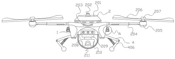
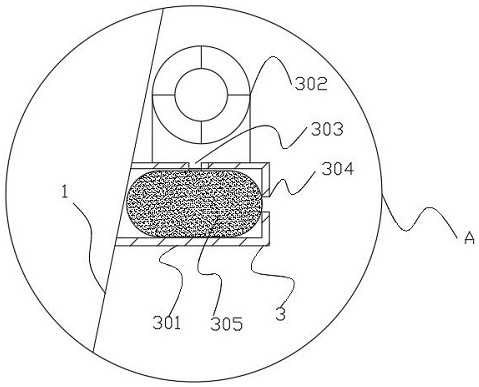
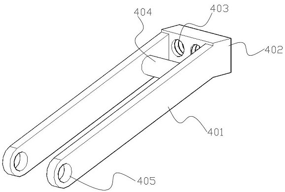
[0027] see Figure 1-6 , the present invention provides a technical solution: an unmanned aerial vehicle landing deceleration damping device with a good deceleration effect, which is easy to install and fixes, including a mounting frame 1, a main frame component 2, an anti-sinking component 3 and a buffer component 4, and the upper part of the main frame component 2 is arranged There is a power cabin 201, and the main frame assembly 2 is located...


PUM


Abstract

The invention discloses an unmanned aerial vehicle landing deceleration damping device convenient to install and fix and good in deceleration effects. The device comprises a mounting frame, a main framework assembly, anti-sinking assemblies and a buffer assembly, wherein a power cabin is arranged above the main framework assembly; the main framework assembly is positioned on the outer side of themounting frame; a gas generator is arranged above the anti-sinking assembly; the anti-sinking assemblies are located on the two sides of the mounting frame. The buffer assembly comprises a fixing rod,an installation block, a threaded hole, an upper shaft column, a fixing bayonet, a foot stand, a shaft block, a swing hole, a lower shaft column, a foam ball, a damper, a damping spring, a baffle anda shaft sleeve. The installation block is arranged at the top end of the fixing rod, a threaded hole is transversely formed in the middle of the mounting block in a penetrating mode, an upper shaft column is arranged on the upper right portion of the fixing rod, a fixing bayonet is formed in the lower left portion of the fixing rod in a penetrating mode, and a user can land more safely and stablythrough the buffer assembly and the anti-sinking assembly.

Description

technical field [0001] The invention relates to the technical field of unmanned aerial vehicles, in particular to an unmanned aerial vehicle landing deceleration damping device which is easy to install and has a good deceleration effect. Background technique [0002] Unmanned aircraft is referred to as "unmanned aerial vehicle", and the English abbreviation is "UAV". Most of the existing UAV devices are only equipped with fixed rigid landing gear, but the speed of the UAV is not easy to control precisely when it lands, and it is easy to have a large impact force when the UAV lands, which will have a certain impact on the precise internal structure of the UAV. and damage, so it is necessary to design a UAV landing deceleration damping device that is easy to install and has a good deceleration effect. Contents of the invention [0003] The object of the present invention is to provide a kind of unmanned aerial vehicle landing deceleration damping device that is easy to inst...

Claims


Application Information

Patent Timeline
IPC IPC(8): B64C25/62B64C25/56B64D45/00B64D45/06B64D47/00
CPCB64C25/62B64C25/56B64D45/00B64D45/06B64D47/00B64U10/10B64U30/20B64U2101/00B64U50/19B64U70/00
Inventor 吴宗霞
Owner 吴宗霞
Learn More