Three-way reversing check valve

A check valve, valve body technology, applied in multi-port valves, valve details, control valves, etc., can solve problems such as must be replaced

Pending Publication Date: 2020-10-23
迦密阀门有限公司
View PDF0 Cites 0 Cited by
  • Summary
  • Abstract
  • Description
  • Claims
  • Application Information

AI Technical Summary

Problems solved by technology

Usually this kind of valve works automatically. Under the action of fluid pressure flowing in one direction, the valve disc opens; Some three-way check val

Method used


Image

  • Three-way reversing check valve
  • Three-way reversing check valve

Examples


Embodiment 1

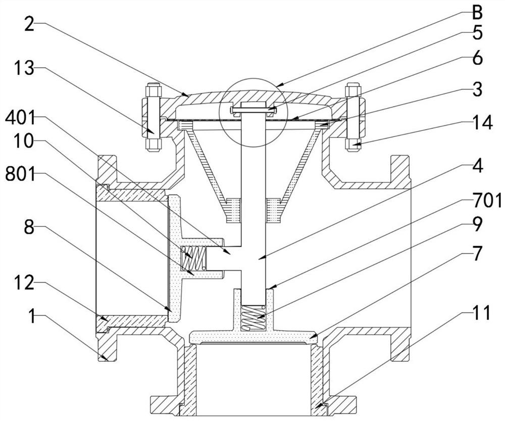
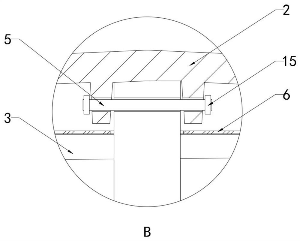
[0024] see Figure 1-2 , including the valve body 1, the shape of the valve body 1 is set in a cross shape, and the top end of the valve body 1 is fixedly connected with the bonnet 2 through the stud 13 and the nut 14, and the lower end surface of the bonnet 2 has a cylindrical The fixed seat and the main valve rod 4 arranged in the vertical direction are fixedly connected to the fixed seat through the insertion rod 5. The main valve rod 4 is sleeved with a fixing part 3 fixedly connected to the valve body 1, and the fixing part 3 has a valve Body 1 and bonnet 2 sandwich the pressure plate 6, the pressure plate 6 is a circular component, and at the same time, after the pressure plate 6 is made of sealing material, the pressure plate 6 is used as a sealing member between the valve cover 2 and the valve body 1, the main valve stem 4 is fixed with an auxiliary valve rod 401 coaxial with the inlet and outlet of the valve body 1, and the end of the main valve rod 4 is provided with...

Embodiment 2

[0026] see Figure 1-2 , the fixing part 3 is a frustum-shaped member, and the bottom end of the fixing part 3 is excessively matched with the main valve stem 4, and the top end of the fixing part 3 has a ring flange, and the flange is engaged with the valve body 1, through the pressure plate 6, the fixing part 3 is firmly installed inside the valve body 1. The valve cavity of the valve body 1 has a circular valve port in the horizontal direction and the vertical direction, the valve port at the top is connected to the valve cover 2, and the first valve disc 7 corresponds to the inlet and has a first valve seat 11 inside it. The two valve discs 8 correspond to the inlet and have a second valve seat 12 inside, so that the valve is a three-way valve. Both the first valve seat 11 and the second valve seat 12 have flanges that engage with the valve body 1 There is an annular sealing member at the position where the flanges of the first valve seat 11 and the second valve seat 12 a...


PUM


Abstract

The invention discloses a three-way reversing check valve. The three-way reversing check valve comprises a valve body, wherein the valve body is arranged in a cross shape, the top end of the valve body is fixedly connected with a valve cover through a stud and a nut, the lower end surface of the valve cover is provided with a cylindrical fixed seat, a main valve rod which is arranged in the vertical direction is fixedly connected into the fixed seat through an insertion rod, a fixed part which is fixedly connected to the valve body sleeves the main valve rod, the fixed part is provided with apressure plate which is clamped by the valve body and the valve cover, an auxiliary valve rod which is coaxial with an inlet and an outlet of the valve body is fixed on the main valve rod, a first valve clack sleeves the end of the main valve rod, and a second valve clack sleeves the end of the auxiliary valve rod. When the three-way reversing check valve is connected to be used, a valve seat canbe disassembled to change the check situation, the three-way reversing check valve can be used as a three-way check valve and also can be used as a one-way check valve, the applicability is high, andthe time and financial resources can be effectively saved for enterprises; and meanwhile, the three-way reversing check valve is good in check effect and capable of precisely controlling the flow direction of a medium.

Description

technical field [0001] The invention relates to the technical field of valves, in particular to a three-way reversing check valve. Background technique [0002] Check valve refers to a kind of valve whose opening and closing parts are circular discs, which can block the reverse flow of medium by acting on its own weight and medium pressure. It is an automatic valve, also known as check valve, one-way valve, return valve or isolation valve. The function of this type of valve is to only allow the medium to flow in one direction and prevent the flow in the opposite direction. Usually this kind of valve works automatically. Under the action of fluid pressure flowing in one direction, the valve disc opens; Some three-way check valves can realize the function of two-way check. When one-way check valve is required and the other is connected in real time, the valve must be replaced. [0003] Therefore, the present invention provides a three-way reversing check valve. Contents o...

Claims


Application Information

Patent Timeline
IPC IPC(8): F16K11/20F16K15/06F16K27/02F16K27/08
CPCF16K11/20F16K15/06F16K27/0209F16K27/0263F16K27/08
Inventor 项光奎
Owner 迦密阀门有限公司
Why Eureka
Try Eureka