Goaf air leakage flow field fixed-time and fixed-point measuring device, and using and measuring method

A technology of measuring device and timing device, applied in the direction of measuring device, fluid dynamics test, machine/structural component test, etc., can solve the unresolved method, theoretical basis and basic data acquisition means of goaf flow field parameters , Can not meet the fine gas control and other issues

Active Publication Date: 2020-10-23
CCTEG SHENYANG RES INST
View PDF9 Cites 2 Cited by
  • Summary
  • Abstract
  • Description
  • Claims
  • Application Information

AI Technical Summary

Problems solved by technology

At present, scientific research institutes and mines mainly propose control plans for the abnormal gas emission that can be observed in the goaf area. The theoretical basis and basic data acquisition methods for the control plan are limited, and the gob bundle tube and numerical simulation are mainly used. As a theoretical support, the data can no longer meet the needs of refined gas control
At present, the research on the distribution characteristics of the goaf flow field at home and abroad has not yet solved the method of directly measuring the flow field parameters of the gob

Method used


Image

  • Goaf air leakage flow field fixed-time and fixed-point measuring device, and using and measuring method
  • Goaf air leakage flow field fixed-time and fixed-point measuring device, and using and measuring method
  • Goaf air leakage flow field fixed-time and fixed-point measuring device, and using and measuring method

Examples


Embodiment 1

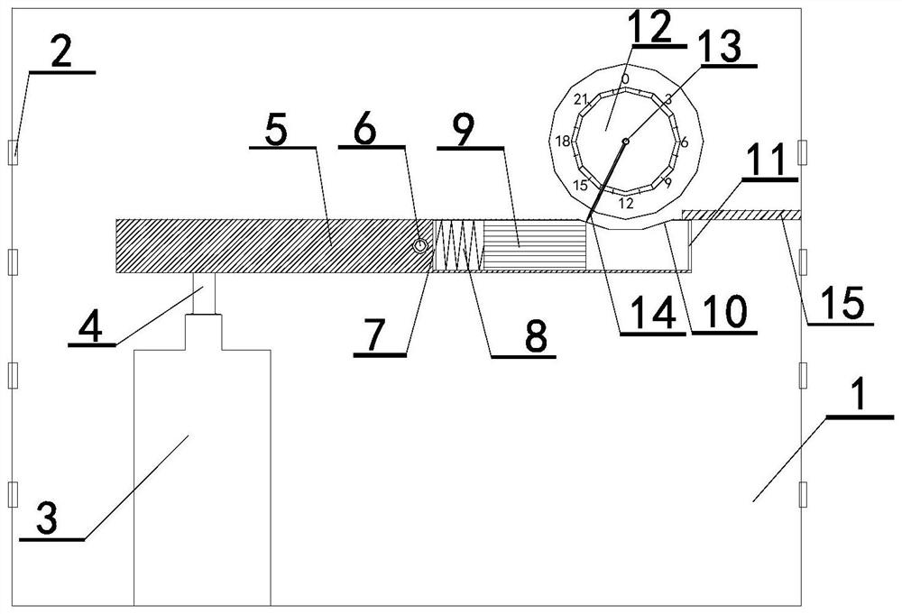
[0031] Such as Figure 1-Figure 3 As shown, the timing and fixed-point measurement device 16 of the goaf air leakage flow field proposed in this embodiment includes a box body 1, and a tracer gas bottle 3, a bottle stopper 4, a lever 5, and a lever support shaft arranged inside the box body 1. 6. The slider 9, the slider baffle 11 and the timing device 12, wherein the box body 1 is provided with a release hole 2, the lever support shaft 6 is connected to the middle section of the lever 5, and the lever 5 is rotatably connected to the lever 5 through the support shaft of the lever 5. Inside the box 1, the top of the tracer gas bottle 3 has a bottle mouth, and the tracer gas bottle 3 is arranged below the first side of the lever 5, and the first side of the lever 5 corresponds to the bottle stopper 4 at the mouth of the tracer gas bottle 3; the lever 5 The second side has a built-in slideway, and the end of the slideway close to the lever support shaft 6 is provided with a sprin...

Embodiment 2

[0037] The method for using the timing and fixed-point measuring device 16 of the air leakage flow field in the goaf proposed in this embodiment uses the timing and fixed-point measuring device 16 for the air leakage flow field in the goaf proposed in Embodiment 1, and the method is as follows:

[0038] The timing and fixed-point measurement device 16 of the air leakage flow field in the goaf is debugged, the bottle stopper 4 of the tracer gas bottle 3 is tightly plugged, the pointer 14 of the timing device is located at the bottom end of the toggle opening 10, and the lever 5 is in a balanced state, which is Timing device 12 is in untimed state, as figure 1 shown.

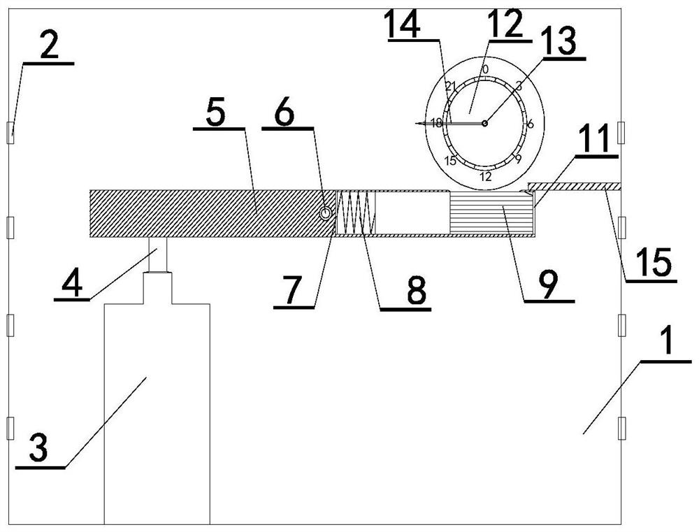
[0039] Tighten the clockwork of the timing device 12 to time the measuring device, the pointer 14 of the timing device leaves the toggle opening 10, under the push of the spring 8, the slide block 9 slides to the right, the toggle opening 10 is blocked by the slide block 9, and the lever 5 is still in a balanced ...

Embodiment 3

[0042] The timing and fixed-point measurement method for the goaf air leakage flow field proposed in this embodiment uses the timing and fixed-point measurement device 16 for the goaf air leakage flow field proposed in Embodiment 1.

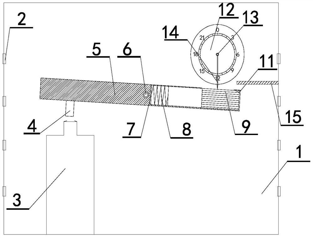
[0043] Such as Figure 4-Figure 6 As shown, when the underground working face of the coal mine is in the mining process, the timed and fixed-point measurement device 16 for the air leakage flow field in the goaf is placed at the tail position behind the hydraulic support of the coal mining face 18, and is placed in the coal mine underground along the direction of the coal mining face 18. When the working face is in the mining process, the timed and fixed-point measurement device 16 of the air leakage flow field in the goaf is placed at the tail position behind the hydraulic support of the coal mining face 18. The distance between the strike direction of the coal working face 18 and the rear tail is Y, such as Figure 4 As shown, where X can be s...


PUM


Abstract

The invention relates to a goaf air leakage flow field measuring technology, in particular to a goaf air leakage flow field fixed-time and fixed-point measuring device. The goaf air leakage flow fieldfixed-time and fixed-point measuring device comprises a box body, wherein a lever is rotatably connected in the box body through a lever supporting shaft rod, and a bottle plug is arranged on the first side, corresponding to a bottle opening of a tracer gas bottle, of the lever; a slideway is arranged in the second side of the lever; a spring is arranged at the end, close to the lever supportingshaft rod, of the slideway; a sliding block is arranged in the slideway, and a poking opening is formed in the top part of one side, away from the lever supporting shaft rod, of the slideway; and a timing device is arranged above the second side of the lever, the timing device is provided with a timing device shaft rod capable of being driven by the timing device to rotate, a timing device pointeris installed on the timing device shaft rod, the timing device shaft rod is opposite to the poking opening, and a moving path at the free tail end of the timing device pointer enters the poking opening forcibly. The goaf air leakage flow field fixed-time and fixed-point measuring device can complete goaf air leakage flow field measurement. The invention further provides a using method of the goafair leakage flow field fixed-time and fixed-point measuring device and a goaf air leakage flow field fixed-time and fixed-point measuring method.

Description

technical field [0001] The invention relates to a goaf air leakage flow field measurement technology, in particular to a timed and fixed-point measurement device for the goaf air leakage flow field and its use and measurement method. Background technique [0002] The combined disasters of gas disasters in coal mines and coal seam spontaneous combustion are concentrated in gobs. The physical characteristics of the goaf are directly related to the characteristics of the flow field, and great progress in gas and fire prevention also depends on an in-depth understanding of its characteristics. At present, the technical means of studying the flow field characteristics of the goaf can be roughly divided into three categories, namely theoretical analysis, numerical simulation and similar simulation. The progress of the research on the characteristics of the goaf flow field is accompanied by the deepening of the understanding of the physical field of the goaf. In the course of its...

Claims


Application Information

Patent Timeline
Patent Type & Authority Applications(China)
IPC IPC(8): G01M10/00
CPCG01M10/00
Inventor 刘春刚孙珍平段宏飞吕文陵刘宝志翁旭泽李铁良孙亮刘浩张东旭唐辉赵国会
Owner CCTEG SHENYANG RES INST
Why Eureka
Try Eureka