
Intelligent plate-type cabinet body structure with hidden conductive joint

A technology of conductive joints and smart boards, which is used in furniture accessories, detachable cabinets, circuits, etc.

Pending Publication Date: 2020-10-27
博洛尼智能科技(青岛)有限公司
View PDF0 Cites 0 Cited by
  • Summary
  • Abstract
  • Description
  • Claims
  • Application Information

AI Technical Summary

Problems solved by technology

The current panel cabinet structure is only suitable for the design of LED decorative lights and a power line. The power line passes through the back panel hole of the panel cabinet and leads to the indoor power supply.

Method used


Image

  • Intelligent plate-type cabinet body structure with hidden conductive joint
  • Intelligent plate-type cabinet body structure with hidden conductive joint
  • Intelligent plate-type cabinet body structure with hidden conductive joint

Examples


Embodiment 1

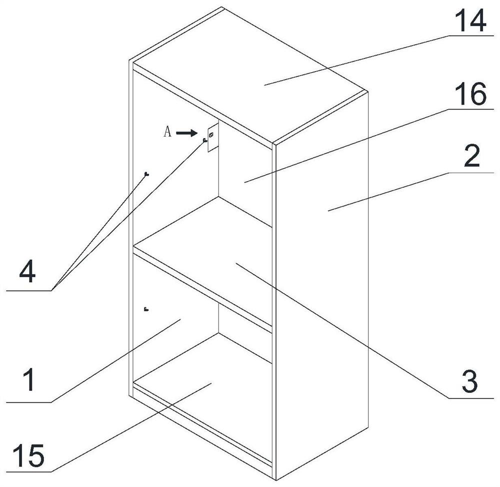
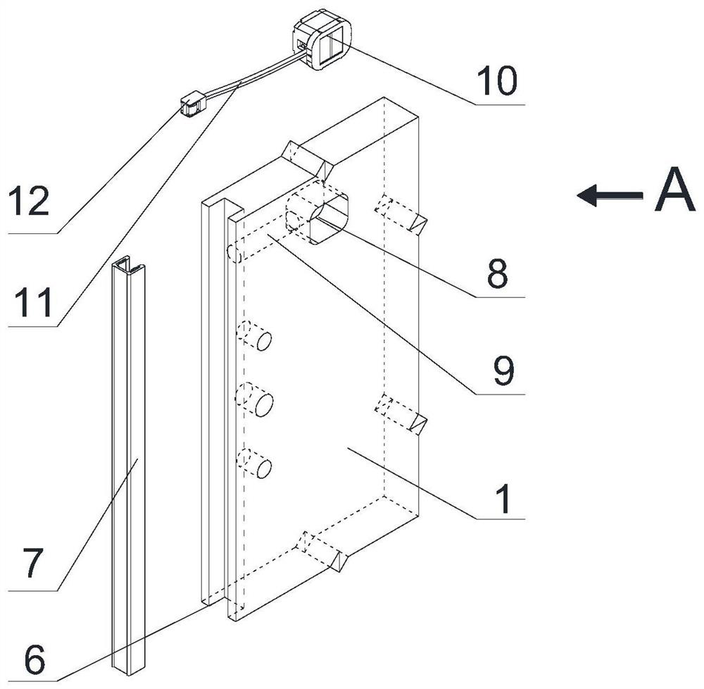
[0058] The following combination figure 1 and figure 2 A specific embodiment of the smart panel cabinet structure with hidden conductive joints described in the present invention is described. The intelligent panel cabinet structure with hidden conductive joints includes: the first side panel 1, the second side panel 2, the first layer panel 3 and the combination of the first panel support;

[0059] The first side plate 1 and the second side plate 2 are oppositely arranged in a direction perpendicular to the ground;

[0060] The first layer plate 3 is detachably linked with the first side plate 1 and the second side plate 2 through the first plate support combination. The first plate support combination includes the first plate support 4 and the second plate support 5. The first plate support 4 Set on the first side plate 1, the second plate support 5 is set on the second side plate 2, the first layer plate 3 can be adjusted and placed in different positions according to th...

Embodiment 2

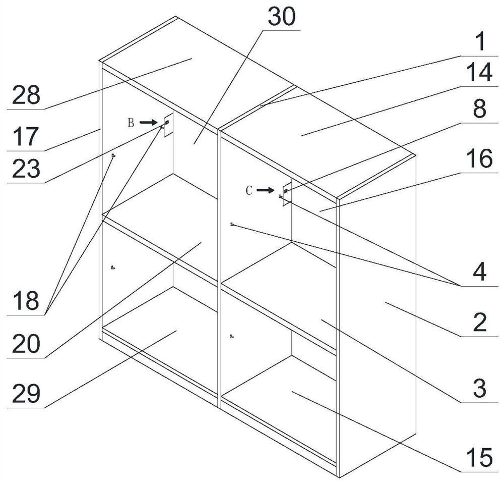
[0079] to combine figure 2 , image 3 and Figure 4 , refer to the decomposition diagram of C area figure 2 , illustrating another embodiment of the present invention, further comprising: a combination of a third side plate 17, a second layer plate 20 and a second plate holder.

[0080] This is another embodiment of the present invention, which includes: a combination of the first side plate 1, the second side plate 2, the first layer plate 3 and the first plate support;

[0081] The first side plate 1 and the second side plate 2 are oppositely arranged in a direction perpendicular to the ground;

[0082] The first layer plate 3 is detachably linked with the first side plate 1 and the second side plate 2 through the first plate support combination. The first plate support combination includes the first plate support 4 and the second plate support 5. The first plate support 4 It is set on the first side plate 1, and the second plate support 5 is set on the second side pla...


PUM


Abstract

The invention discloses an intelligent plate-type cabinet body structure with a hidden conductive joint. The intelligent plate-type cabinet body structure comprises a first side plate, a second side plate, a first laminate and a first plate support combination, the first side plate comprises a concave first mounting groove formed in one end of the first side plate in the direction perpendicular tothe ground, a concave first conductive groove oppositely clamped with the first mounting groove, a first through hole penetrating through the first side plate, and a second through hole formed in thedirection from the first conductive groove to the first through hole; the first side plate further comprises a first conductive element, and the first conductive element comprises a first conductivesheet, a first wire and a first conductive plug; a driver is provided at one end of the first conductive groove near the ground, one end of the driver is connected with a first copper bar in the firstconductive groove, and the other end of the driver is connected with a power supply. The electronic components are arranged on the first layer plate, and the circuits are arranged in the first side plate and the first layer plate, so that the wiring problem of the electronic components is solved, and attractiveness and safety are achieved.

Description

technical field [0001] The invention relates to the field of panel cabinets, in particular to an intelligent panel cabinet structure with hidden conductive joints. Background technique [0002] The panel cabinet is disassembled and assembled on the basis of panels, and is used for storing and organizing objects. The current panel cabinet structure is only suitable for the design of LED decorative lights and a power cable. The power cable passes through the back panel hole of the panel cabinet and leads to the indoor power supply. If the board-type cabinet is equipped with multiple smart products, it cannot be penetrated into the back panel hole of the cabinet at the same time to solve the connection problem of hiding the power cord of the smart product, and it is also impossible to hide the power cord of the smart product and meet the safety requirements of household electricity. [0003] Therefore, it is an urgent problem to provide an intelligent panel cabinet structure w...

Claims


Application Information

Patent Timeline
Patent Type & Authority Applications(China)
IPC IPC(8): A47B47/00A47B97/00H01R24/76
CPCA47B47/00A47B97/00H01R24/76A47B2220/0091
Inventor 蔡明蔡兴国王庆彦吕青
Owner 博洛尼智能科技(青岛)有限公司
Learn More