Multi-channel wireless luminosity testing system and method

A test system, multi-channel technology, applied in the field of photometric testing of aircraft lighting systems, can solve problems such as spending a lot of manpower and time, unable to complete on-site testing, on-site testing difficulty, etc., to improve test efficiency, test light intensity distribution, The effect of fast light intensity distribution

Pending Publication Date: 2020-06-16
SHANGHAI AVIATION ELECTRIC
View PDF0 Cites 2 Cited by
  • Summary
  • Abstract
  • Description
  • Claims
  • Application Information

AI Technical Summary

Problems solved by technology

[0003] At present, the test problem of the spatial distribution of luminous intensity in the laboratory has been solved. For the test of the spatial distribution of luminous intensity of large-scale lighting equipment on site after the aircraft lighting system is installed, a general-purpose illuminance meter with a special bracket for the site is still used for testing. Due to On-site power supply, signal transmission, location and other complex conditions bring great difficulty and inconvenience to on-site testing, resulting in inability to complete on-site testing or requiring a lot of manpower and time

Method used


Image

  • Multi-channel wireless luminosity testing system and method
  • Multi-channel wireless luminosity testing system and method
  • Multi-channel wireless luminosity testing system and method

Examples


Embodiment Construction

[0019] The present invention will be described in further detail below through specific embodiments in conjunction with the accompanying drawings. It should be noted here that the descriptions of these embodiments are used to help understand the present invention, but are not intended to limit the present invention. In addition, the technical features involved in the various embodiments of the present invention described below can be combined with each other as long as they do not constitute a conflict with each other.

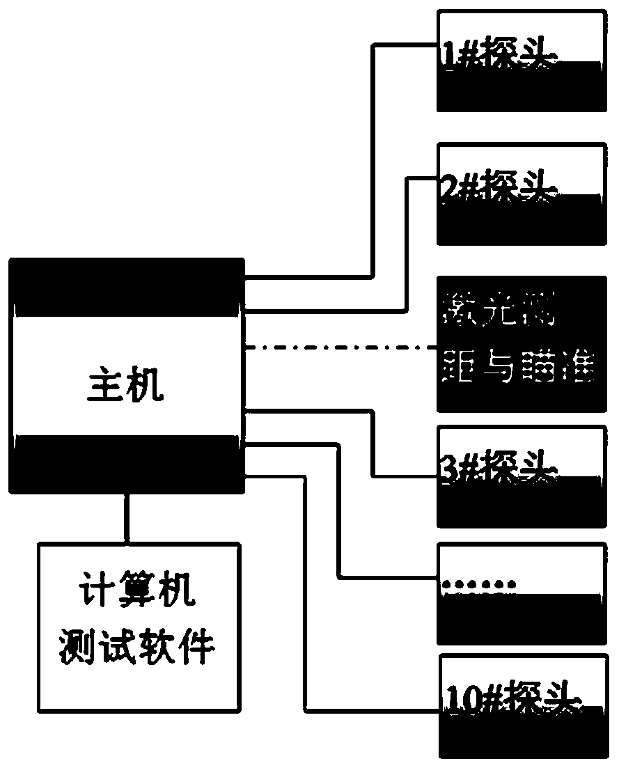
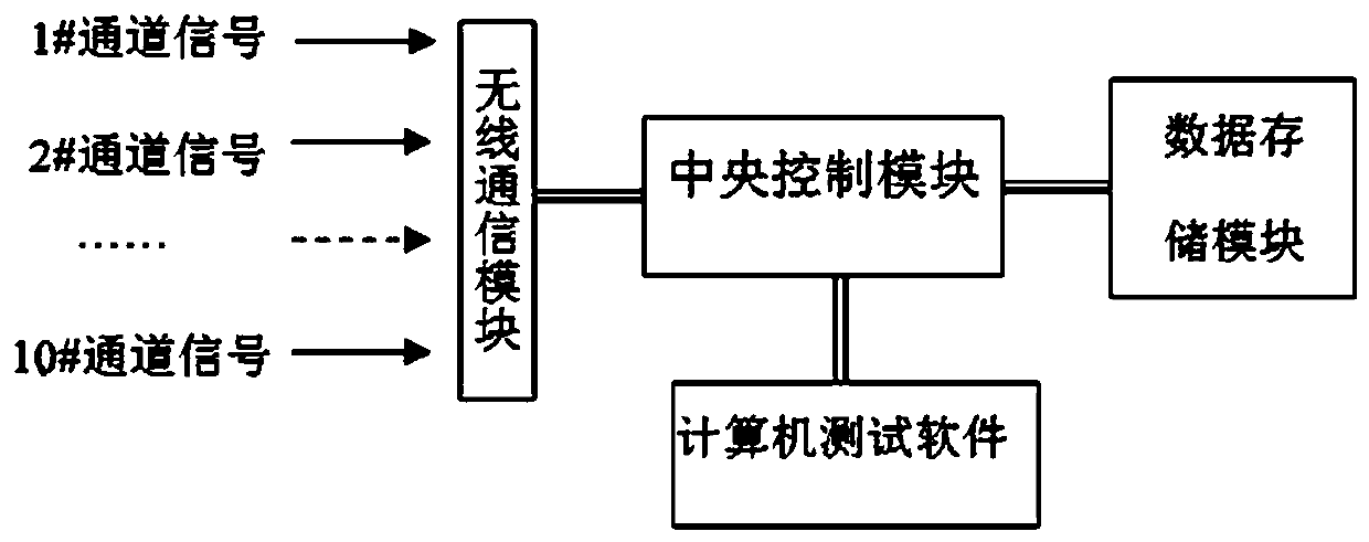
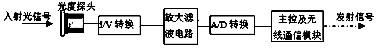
[0020] See Figures 1 to 4 , the multi-channel wireless photometric testing system provided by the present invention. It consists of a host, 10-way probes and a small bracket, a laser range finder and a computer measurement software. The host is mainly composed of a data storage module, a multi-channel wireless communication module, and a central control module. The host performs functions such as wireless control of 10-way probes, reading information, stor...


PUM


Abstract

The invention discloses a multi-channel wireless luminosity test system and method. The system comprises a plurality of probe devices which are disposed at the periphery of a lighting device and a central control module communicated with the probe devices in a wireless manner. The multi-channel wireless luminosity test system and method have the beneficial effect that the problem of testing the spatial distribution of the luminous intensity of the large-scale lighting equipment on site is solved.

Description

technical field [0001] The invention relates to the field of photometric testing of aircraft lighting systems, in particular, a multi-channel wireless photometric testing system and method. Background technique [0002] The spatial distribution of the luminous intensity of the lighting equipment of the aircraft lighting system, especially the external lighting system, describes how the luminous intensity of the equipment changes with the spatial position or angle, and is the core index for evaluating the quality of the lighting source in the lighting field. [0003] At present, the test problem of the spatial distribution of luminous intensity in the laboratory has been solved. For the test of the spatial distribution of luminous intensity of large-scale lighting equipment on site after the aircraft lighting system is installed, a general-purpose illuminance meter with a special bracket for the site is still used for testing. Due to On-site power supply, signal transmission,...

Claims


Application Information

Patent Timeline
IPC IPC(8): G01J1/42G08C17/02
CPCG01J1/4228G08C17/02G01J2001/4247
Inventor 李薇占春莲
Owner SHANGHAI AVIATION ELECTRIC
Why Eureka
Try Eureka