IT device cabinet U bit management method and U bit manager

A technology for equipment cabinets and management methods, which is applied in the field of IT equipment cabinet U-position management methods and U-position managers, can solve problems such as insufficient intelligence in management methods, high requirements for communication networks and background servers, and large data transmission volumes, and achieve improved Management efficiency, convenient on-site operation, and the effect of reducing data

Active Publication Date: 2016-09-07
华西信息工程江苏有限公司
View PDF5 Cites 14 Cited by
  • Summary
  • Abstract
  • Description
  • Claims
  • Application Information

AI Technical Summary

Problems solved by technology

[0007] The technical problem to be solved by the present invention is that in the prior art, the management method of the U-position automatic system of the IT equipment cabinet is not intelligent enough, and the system needs to return the status information of each U-position in the cabinet every time it is detected and updated, and the amount of data transmission is large. Higher requirements on communication network and background server

Method used


Image

  • IT device cabinet U bit management method and U bit manager
  • IT device cabinet U bit management method and U bit manager
  • IT device cabinet U bit management method and U bit manager

Examples


Embodiment 1

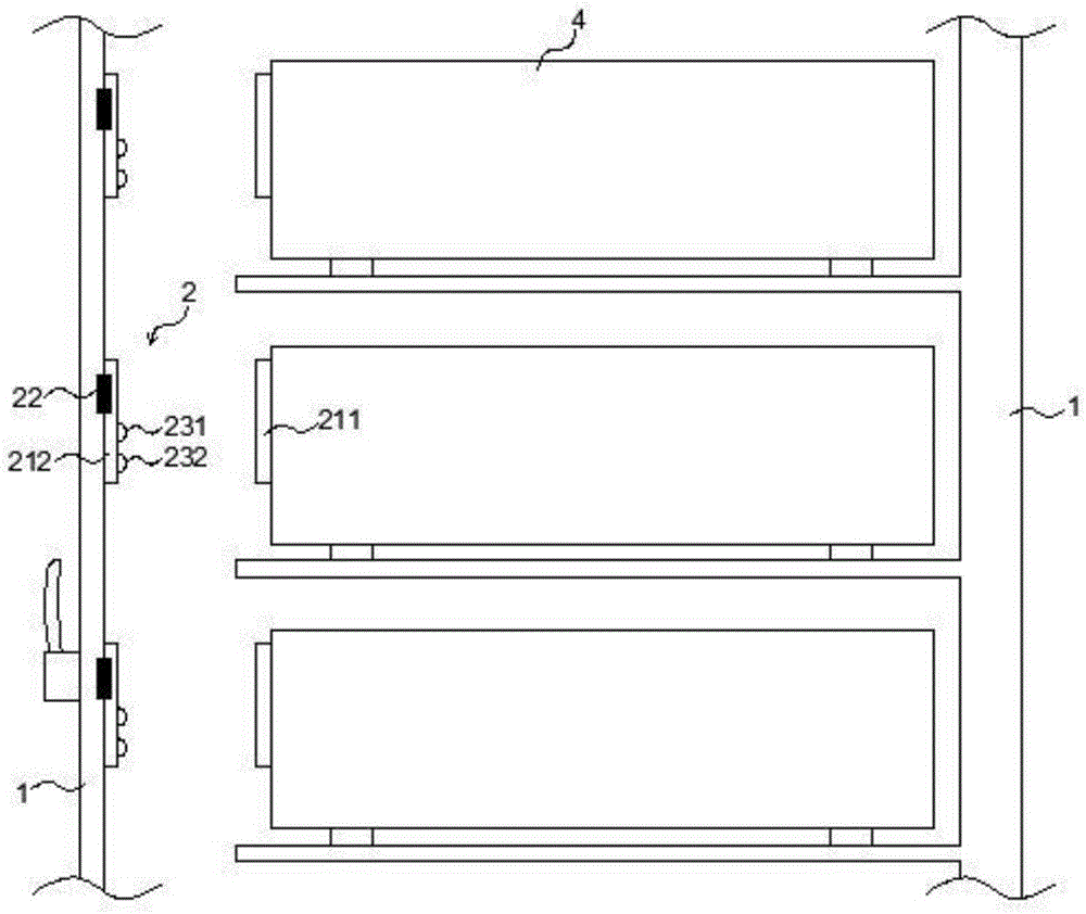
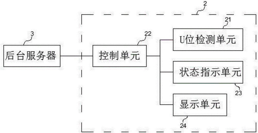
[0033] like figure 1 , image 3 , Figure 4 and Figure 5 As shown, the U bit manager 2 of the present embodiment includes an RFID tag 211, an RFID reader 212, a control unit 22, a status indication unit 23 and a display unit 24, the RFID tag 211 is installed on the IT equipment 4, and the RFID tag 211 stores Corresponding to the attribute information of the IT equipment 4, the RFID reader 212, the control unit 22 and the status indication unit 23 are installed on the cabinet 1, and each U position in the cabinet 1 is equipped with a U position manager 2, and the U position manager 2 in the The RFID reader 212 only reads the RFID tags 211 on the IT equipment 4 in the corresponding U position.

[0034] The installation position of each control unit 22 in the machine room is fixed, and the control unit 22 stores the position information of the control unit 22 . Background server 3 establishes the U position information list in the computer room according to the position info...

Embodiment 2

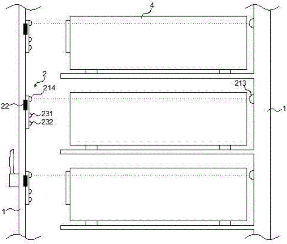
[0039] like Figure 2 to Figure 5 As shown, the U-bit manager 2 of the present embodiment includes an infrared transmitter 213, an infrared receiver 214, a control unit 22, a status indication unit 23 and a display unit 24, and the infrared transmitter 213 and the infrared receiver 214 are respectively installed on the IT equipment 4, the control unit 22 and the status indication unit 23 are installed on the cabinet 1. Each U-position in the cabinet 1 is installed with a U-position manager 2 , and the infrared receiver 214 in the U-position manager 2 is connected to the control unit 22 .

[0040] The difference between the U bit manager 2 of the present embodiment and the U bit manager 2 of Embodiment 1 is that the state information detection method of the U bit is different, and whether the U bit manager 2 of the present embodiment can receive it through the infrared receiver 214 The signal of the infrared transmitter 213 is used to determine whether the U position is in use...


PUM


Abstract

The present invention discloses an IT cabinet U bit management method and a U bit manager. According to the method, a management terminal, i.e. a U bit manager is used to receive and store a background task, and then the task is compared with U bit state information, and then the U bit state information or preset information is sent to a background server according to a comparison result and the task or not. The U bit manager disclosed by the present invention is a management terminal with a self-determining function, wherein the U bit manager compares detected current U bit state information with stored last-time U bit state information, and returns state information of a U bit of which state information is changed to the background server, so as to update a U bit information list. Therefore, data returned from the management terminal to the background is greatly decreased, the demands for the communication network and the background server are reduced, and the IT device management efficiency is improved.

Description

technical field [0001] The invention relates to the field of IT equipment cabinets, in particular to a U-position management method and a U-position manager for IT equipment cabinets. Background technique [0002] The mechanical installation dimensions of IT equipment comply with GB / T3047.2-92 and JB / T 10324-2002 standards, and the height is measured by "U" digits. U is the abbreviation of unit, which is a special unit of measurement for the height occupied by IT equipment installed in the international cabinet. The U-position refers to the small space within the cabinet that accommodates each IT device. [0003] The cabinets of IT equipment are usually stored centrally in a computer room with good electromagnetic environment and continuous cooling. With the continuous development of IT technology, these centralized storage of a large number of IT equipment often need to be replaced, moved, maintained or upgraded. It is an important content of IT equipment management to a...

Claims


Application Information

Patent Timeline
Patent Type & Authority Applications(China)
IPC IPC(8): G06F11/30G06F11/32
CPCG06F11/3055G06F11/325
Inventor 林奎
Owner 华西信息工程江苏有限公司
Why Eureka
Try Eureka