Novel electromagnetic type vibration isolator with adjustable negative stiffness

A negative stiffness, electromagnetic technology, applied in the functional characteristics of spring/shock absorber, magnetic spring, spring/shock absorber, etc., can solve the problem of increasing design workload, difficult design of passive support mechanism inside the vibration isolator, system problems such as reduced reliability

Active Publication Date: 2020-10-27
NUCLEAR POWER INSTITUTE OF CHINA
View PDF6 Cites 4 Cited by
  • Summary
  • Abstract
  • Description
  • Claims
  • Application Information

AI Technical Summary

Problems solved by technology

[0004] However, the core realization technology of this kind of negative stiffness is to use the electromagnetic attraction between the magnetic teeth to construct the axially unstable force between the internal mover and the external stator. In practical applications, it is difficult to design the passive support mechanism inside the vibration isolator. Therefore, if you want to use this negative stiffness

Method used


Image

  • Novel electromagnetic type vibration isolator with adjustable negative stiffness
  • Novel electromagnetic type vibration isolator with adjustable negative stiffness
  • Novel electromagnetic type vibration isolator with adjustable negative stiffness

Examples


Embodiment 1

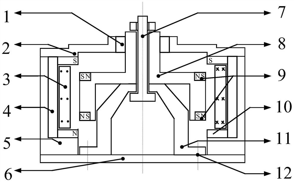
[0040] Such as figure 1 As shown, a new type of electromagnetic vibration isolator with adjustable negative stiffness includes a stator housing 5, a mover 8 arranged in the inner cavity of the stator housing 5 and movable along the longitudinal axis of the stator housing 5, assembled A positive stiffness component that acts as a positive stiffness on the mover 8 below the mover 8,

[0041] It also includes a permanent magnet 9 mounted on the outer wall of the mover 8, arranged on the first layer along the longitudinal axis of the mover 8, and a permanent magnet 9 arranged on the second layer, the permanent magnet 9 of the first layer and the permanent magnet of the second layer The polarity end face of the permanent magnetic field of 9 faces the radial direction, and the polarity of the permanent magnet 9 of the first layer is opposite to that of the permanent magnet 9 of the second layer;

[0042] It also includes a coil assembly assembled on the inner wall of the stator hou...

Embodiment 2

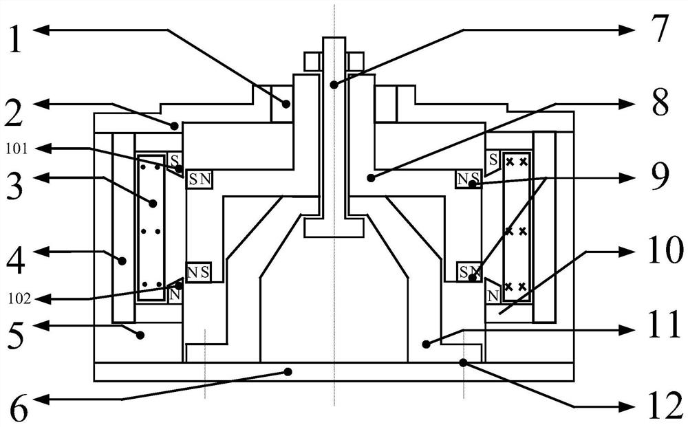
[0051] Although in embodiment 1, in order to construct the repulsive force relationship, the outer end faces of the coil yoke at the upper and lower ring openings will form a polarity, and when the negative stiffness and positive stiffness are balanced, the coil yoke will be positive to its corresponding permanent Magnets, therefore, the effective travel range of its negative stiffness is related to the size of the polar end face of the coil yoke or permanent magnet, and in order to miniaturize the size, and to seek a better repulsive force relationship and a good negative stiffness effective travel range. This embodiment is constructed on the basis of Embodiment 1, such as figure 2 As shown, the further technical solution is: the end of the coil yoke 10 facing the mover at the upper ring mouth is bent downward and extended to form an upper yoke tongue 101, and the coil yoke 10 at the lower ring mouth is bent upward at the end facing the mover. The lower yoke tongue 102 is fo...

Embodiment 3

[0054] Such as image 3 As shown, further, in order to overcome the problem of weakening of the above-mentioned repulsive force, the end faces of the upper yoke iron tongue 101 and the lower yoke iron tongue 102 are treated with the splitting tip used in the present invention, specifically: the lower end surface of the upper yoke iron tongue is an upwardly inclined slope 1. The upper end face of the lower yoke tongue is a downwardly inclined slope. At this time, the projected size of the magnetic field air gap between the upper yoke tongue and the lower yoke tongue adjacent to the outer surface of the mover on the longitudinal axis is smaller than that far away from Based on the projection size of the inner surface of the mover on the longitudinal axis, the projected size of the outer surface of the lower yoke tongue and upper yoke tongue adjacent to the mover side on the longitudinal axis is larger than the inner surface far away from the mover side in the longitudinal directi...


PUM


Abstract

The invention discloses a novel electromagnetic type vibration isolator with the adjustable negative stiffness. The novel electromagnetic type vibration isolator comprises a stator shell (5), a mover(8) and a positive stiffness component, wherein the positive stiffness component is assembled below the mover (8) and plays a positive stiffness role for the mover (8). The novel electromagnetic typevibration isolator further comprises permanent magnets (9) arranged on the first layer and permanent magnets (9) arranged on the second layer, wherein the permanent magnets (9) are assembled on the outer side wall of the mover (8) and arranged in the longitudinal axis direction of the mover (8). The facing direction of the polarity end face of a permanent magnetic field formed by the permanent magnets (9) arranged on the first layer and the permanent magnets (9) arranged on the second layer is the radial direction, and the permanent magnets (9) arranged on the first layer and the permanent magnets (9) arranged on the second layer are opposite in polarity. The novel electromagnetic type vibration isolator further comprises a coil assembly, wherein the coil assembly is assembled on the innerside wall of the stator shell (5). The coil assembly comprises a coil (3) and coil yokes (10), wherein the winding axis of the coil (3) is the longitudinal axis, and the coil yokes (10) are arrangedat an upper coil opening and a lower coil opening of the coil. The vibration isolator is arranged based on the electromagnetic acting force among the permanent magnets and electromagnets.

Description

technical field [0001] The invention relates to the field of vibration isolator design, and relates to a novel electromagnetic vibration isolator with adjustable negative stiffness. Background technique [0002] The quasi-zero stiffness vibration isolation technology can provide a lower dynamic stiffness on the premise of ensuring a higher static stiffness, thereby not only ensuring the static support stability of the system but also achieving a lower first-order natural frequency, and the low-frequency vibration isolation effect of the system better. Considering the superior performance of the quasi-zero stiffness vibration isolator, it has received more and more research and exploration in recent years. Traditional quasi-zero-stiffness vibration isolators mostly use a spring combination structure or a permanent magnet combination spring to achieve the negative stiffness effect, but the non-adjustability of the achieved negative stiffness limits its application to a certai...

Claims


Application Information

Patent Timeline
IPC IPC(8): F16F6/00
CPCF16F6/00F16F2228/063F16F2228/066
Inventor 韩超李鑫刘桂祥邵骁麟刘天彦姚迪林松张鲲孙磊李朋洲
Owner NUCLEAR POWER INSTITUTE OF CHINA
Why Eureka
Try Eureka