Charging pile plug resistor detection method

A detection method and resistance detection technology, applied in circuits, measuring electricity, measuring devices, etc., can solve problems such as wrong use of charging piles, threshold setting deviation, and resistance detection methods that cannot be well solved.

Inactive Publication Date: 2020-10-27
JIANGSU UNIV
View PDF0 Cites 0 Cited by
  • Summary
  • Abstract
  • Description
  • Claims
  • Application Information

AI Technical Summary

Problems solved by technology

However, due to factors such as bumps and scratches that may occur when installing the charging pile, the ground potential of the charging pile may shift. During use, this measurement method will encounter the influence of ground potential drift, which will make the measured voltage inaccurate, and eventually lead to resistance. Incorrect calculation of the resistance value
Moreover, in the process of production and development, the charging pile used when setting the threshold may also have a ground potential offset phenomenon, resulting in a deviation in the threshold setting, and an error occurs when using it on a correctly installed charging pile.
Due to the improper operation of the charging pile installation process, the ground potential drift often occurs, which has also become a reason why some electric vehicles cannot be charged.
The existing charging pile plug resistance detection method cannot solve this problem well

Method used


Image

  • Charging pile plug resistor detection method
  • Charging pile plug resistor detection method
  • Charging pile plug resistor detection method

Examples


Embodiment Construction

[0019] The present invention will be further described below in conjunction with the accompanying drawings and specific embodiments. It should be pointed out that the technical solution and design principles of the present invention will be described in detail below only with an optimized technical solution, but the protection scope of the present invention does not limited to this.

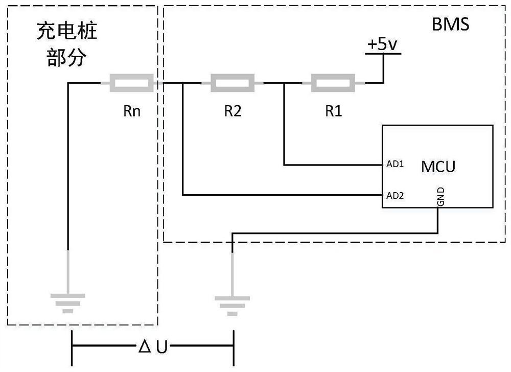
[0020] like figure 1 The detection circuit structure schematic diagram shown, the detection circuit of the present invention includes protection resistor R 1 , The measured resistance R 2 , Charging pile plug resistance R n , the MCU responsible for reading the potential value and calculation, the detection power provided by the BMS, the protection resistor R 1 , The measured resistance R 2 , Charging pile plug resistance R n in series, the MCU is connected to the measured resistor R 2 Both ends, used to measure the measured resistance R 2 Potential values ​​at both ends. When the car cha...


PUM


Abstract

The invention belongs to the technical field of electric automobile charging, and particularly relates to a charging pile plug resistor detection method. After an automobile battery is connected witha charging pile, a BMS provides a power supply to connect the detection circuit, the two ends of the detected resistor are connected with two A / D conversion interfaces of an MCU, the MCU obtains potential values at the two ends of the detected resistor, calculates the resistance value of the charging pile plug resistor and sends the resistance value to the BMS system, and the BMS system determinesvarious index values in a charging strategy according to the resistance value and starts charging. According to the invention, the influence of grounding potential drifting can be filtered, the resistance value of the charging pile plug resistor can be accurately obtained, the problem that charging cannot be conducted due to the fact that the BMS detects the charging pile plug resistor mistakenlyis solved, and the situation that a threshold value is set mistakenly due to grounding potential drifting is avoided; and two analog-to-digital conversion ports are used for acquiring required data,and a circuit does not need to be changed, so that the detection is enabled to be quicker, and the measured resistance value is more accurate.

Description

technical field [0001] The invention belongs to the technical field of electric vehicle charging, and in particular relates to a detection method for the plug resistance of a charging pile. Background technique [0002] In the current electric vehicle charging technology, the charging pile can automatically switch the plug resistance of the charging pile according to the load capacity of the connected charging cable. Generally, there are several options such as 100Ω, 220Ω, 680Ω, 1.5KΩ and 2.2KΩ. (Battery Management System) will detect the charging pile plug resistance. By measuring the resistance, the load capacity of the charging cable is determined according to the set resistance threshold, so as to determine various charging indicators, including charging pile output indicators and indicators used for BMS system monitoring charging process, etc. The charging control strategy of the BMS system includes four parts: adjusting charging current according to temperature change...

Claims


Application Information

Patent Timeline
IPC IPC(8): H01R13/66G01R31/364
CPCG01R31/364H01R13/6683
Inventor 马世典侯桐江浩斌韩牟
Owner JIANGSU UNIV
Why Eureka
Try Eureka