Low-temperature oscillation charging control circuit and method for storage battery pack

A charging control method and battery pack technology, which are applied in battery circuit devices, battery charging management, safety/protection battery circuits, etc., can solve problems such as the oscillation circuit cannot provide continuous resonance current and cannot meet the requirements of low-temperature charging, etc. Achieve the effect of reducing equivalent internal resistance and increasing temperature

Pending Publication Date: 2019-08-20
绍兴和欣控制科技有限公司
View PDF1 Cites 4 Cited by
  • Summary
  • Abstract
  • Description
  • Claims
  • Application Information

AI Technical Summary

Problems solved by technology

[0004] The purpose of the present invention is to provide a battery pack low-temperature oscillation charging control circuit and control method to solve the problem that the existing oscillation circuit cannot meet the requirements of low-temperature charging due to the inability to provide continuous resonant current, so that the battery pack can truly realize charging in a low-temperature environment. fully charged

Method used


Image

  • Low-temperature oscillation charging control circuit and method for storage battery pack
  • Low-temperature oscillation charging control circuit and method for storage battery pack
  • Low-temperature oscillation charging control circuit and method for storage battery pack

Examples


Embodiment 1

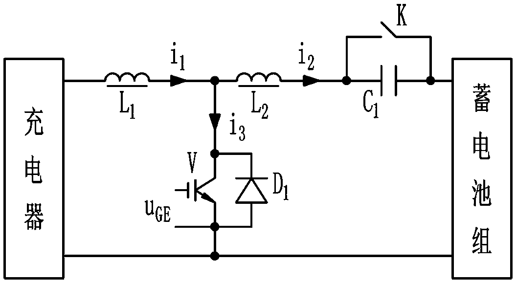
[0027] Such as figure 1 As shown, the battery pack low-temperature oscillation charging control circuit of the present invention connects a separately excited oscillation circuit between the charger and the battery pack. The oscillating circuit is an inductor L connected in series at the positive output terminal of the charger 1 , inductance L 2 and capacitance C 1 Connected to the positive terminal used to connect the battery pack, at the capacitor C 1 There is a switch K connected in parallel at both ends of the charger; the negative output terminal of the charger is divided into two routes, and one route passes through the anti-parallel switching device V and diode D 1 After connected to the series inductor L 1 with inductance L 2 On the connecting node between them, the other is connected to the negative terminal for connecting the battery pack, and the control pole of the switching device V is connected to the switch control circuit through the driving circuit.

[0...

Embodiment 2

[0037] Such as Figure 5 As shown, the control circuit structure of this embodiment is the same as that of Embodiment 1 (see figure 1 ) are basically the same, the difference is that the inductance L is added at the front end of the oscillation circuit 0 and capacitance C 0 composed of low-pass filters. This is due to the inductance L 1 current i in 1 large fluctuations (see Figure 4 (b)), may affect the stable operation of the charger, adding the inductance L 0 and capacitance C 0 After forming a second-order low-pass filter, the inductance L can be effectively reduced 1 Medium current i 1 The impact of fluctuations on the charger makes the charger output a stable DC current. The added low-pass filter composed of inductors and capacitors can be one group or several groups connected in series; it can be a second-order low-pass filter composed of inductors and capacitors, or other forms of low-pass filtering device.

[0038] The oscillation working process of this e...

Embodiment 3

[0040] Such as Image 6 As shown, this embodiment gives an example of the structure of a low-temperature oscillation charging control circuit that uses a single-chip microcomputer to form a switch control circuit. In this embodiment, the integrated circuit chip PIC12F675 is used as the main body of the pulse width modulation circuit to replace the function of the 555 timer described in Embodiment 1. In addition, by detecting the charging and discharging current of the battery pack, automatic switching between oscillation and charging can be realized; by detecting the temperature of the battery pack, automatic switching between oscillation and charging can also be realized.

[0041] If the oscillating circuit needs to achieve intelligent control at the same time, or use the resources of the charger to realize the intelligent control of the entire charging system, only a few detection components need to be added to the hardware part, such as a temperature sensor for detecting th...


PUM


Abstract

The invention relates to a low-temperature oscillation charging control circuit and method for a storage battery pack. According to the control circuit, the positive output end of a charger is connected to a positive wiring terminal used for connecting the storage battery pack through an inductor L1, an inductor L2 and a capacitor C1 which are connected in series, and the capacitor C1 is connectedto two ends of a switch K in parallel; the negative output end of the charger is divided into two paths, one path passes through a switching device V and a diode D1, which are in reverse parallel connection, and is connected to a connection node between the inductor L1 and the inductor L2 which are connected in series, the other path is connected to a negative wiring terminal used for connectingthe storage battery pack, and a control pole of the switching device V is connected to a switch control circuit through a driving circuit. The internal resistance increases due to the polarization orvulcanization of the storage battery in the low temperature environment, which results in a phenomenon of no charge or insufficient charge. The oscillation charging method of the invention enables high-frequency alternating current flowing through the battery pack to greatly reduce or eliminate the polarization or vulcanization of the batteries, thereby eliminating the internal resistance of the batteries caused by the low temperature in a targeted manner, reducing the internal resistance of the batteries, promoting the consistency of the internal resistance of the batteries, and further activating the batteries and prolonging the service life of the storage battery pack.

Description

technical field [0001] The invention relates to a storage battery charging device, in particular to a storage battery pack low-temperature oscillation charging control circuit and control method. Background technique [0002] In order to solve the problem that the battery cannot be fully charged in a low-temperature environment and affect the normal use of electric equipment (such as electric vehicles), CN104935059A patent discloses a low-temperature charging method and charging equipment for electric vehicles. The idea of ​​this method is normal charging plus circuit oscillation, that is, under low temperature conditions, the electric vehicle is charged normally for a period of time, then the charging circuit is disconnected and the oscillation circuit is connected. After the oscillation works for a certain time, the oscillation circuit is disconnected and the charging circuit is connected. After the electric vehicle is normally charged for a certain period of time, the cha...

Claims


Application Information

Patent Timeline
Patent Type & Authority Applications(China)
IPC IPC(8): H02J7/00
CPCH02J7/0022H02J7/0026
Inventor 韩伍林侯增敏郝雄毅
Owner 绍兴和欣控制科技有限公司
Why Eureka
Try Eureka