Non-contact heart rate monitoring method and system

A heart rate monitoring, non-contact technology, applied in the measurement of pulse rate/heart rate, diagnostic recording/measurement, medical science, etc., can solve problems such as inability to calculate heart rate

Active Publication Date: 2020-10-30
HEFEI UNIV OF TECH
View PDF7 Cites 4 Cited by
  • Summary
  • Abstract
  • Description
  • Claims
  • Application Information

AI Technical Summary

Problems solved by technology

[0006] Aiming at the deficiencies of the prior art, the present invention provides a non-contact heart rate monitoring method and system, which solves the problem that data other than the frequency value corresponding to the maximum value of the frequency domain response cannot be fully utilized in the time domain signal and frequency domain signal. Technical issues with calculating heart rate

Method used


Image

  • Non-contact heart rate monitoring method and system
  • Non-contact heart rate monitoring method and system
  • Non-contact heart rate monitoring method and system

Examples


Embodiment 1

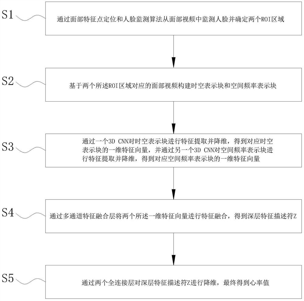
[0067] Such as Figure 1-2 As shown, the present invention provides a non-contact heart rate monitoring method, the method is executed by a computer, the method includes S1-S5:

[0068] S1, monitor the face from the facial video and determine two ROI regions through facial feature point positioning and face detection algorithm;

[0069] S2. Construct a spatiotemporal representation block and a spatial frequency representation block based on the facial videos corresponding to the two ROI regions;

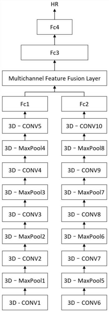
[0070] S3. Perform feature extraction and dimensionality reduction on the spatiotemporal representation block through a 3D CNN to obtain a one-dimensional feature vector corresponding to the spatiotemporal representation block, and perform feature extraction and dimensionality reduction on the spatial frequency representation block through another 3D CNN to obtain the corresponding spatial frequency represents the one-dimensional feature vector of the block;

[0071] S4. Perform fe...

Embodiment 2

[0123] The present invention also provides a non-contact heart rate monitoring system, including a face monitoring module, an ROI area screening module, a spatiotemporal representation block generation module, a spatial frequency representation block generation module, and a multi-channel feature fusion heart rate monitoring network module;

[0124] The human face monitoring module is used to monitor the human face in the facial video, and monitor the coordinates of facial feature points;

[0125] The ROI region screening module is used to filter out two regions as ROI regions from the coordinates of facial feature points;

[0126] The spatio-temporal representation block generation module includes a time-domain signal extraction unit and a spatio-temporal sub-block construction unit; the time-domain signal extraction unit is used to adjust the resolution of the facial video corresponding to the ROI area to H ROI1 *W ROI1 and H ROI2 *W ROI2 , to obtain the time domain signa...


PUM


Abstract

The invention provides a non-contact heart rate monitoring method and system, and relates to the technical field of heart rate monitoring. The method comprises the following steps of: monitoring a face from a face video through face feature point positioning and a face monitoring algorithm, and determining two ROI regions; obtaining a time domain signal of the nth pixel in the RGB color gamut space based on the face video corresponding to the ROI, and obtaining a space-time representation block of the original face video based on the time domain signal; obtaining a frequency domain signal by using fast Fourier transform and a band-pass filter; obtaining a spatial frequency representation block of the original face video according to the frequency domain signal; and extracting features andreducing dimensions of the space-time representation block and the space frequency representation block through a multi-channel feature fusion heart rate monitoring network, and calculating a heart rate value. The technical problem that the heart rate cannot be calculated by fully utilizing the data except the frequency value corresponding to the frequency domain response maximum value in the timedomain signal and the frequency domain signal in the prior art is solved, and the accuracy of heart rate estimation can be effectively improved.

Description

technical field [0001] The invention relates to the technical field of heart rate monitoring, in particular to a non-contact heart rate monitoring method and system. Background technique [0002] When monitoring the heart rate of patients with infectious diseases, the use of non-contact monitoring methods can effectively avoid contact between medical staff and patients, and reduce the risk of infection for medical staff. [0003] Most of the existing non-contact heart rate monitoring methods are based on visual image information technology. For example, the invention patent No. 2015107410069 discloses a non-contact heart rate monitoring method. The internal video image data is used to identify the face in the image data, and calculate the image of the region of interest of the face; then calculate the difference value of the red and green components of the image of the region of interest through the time-domain difference color change amplification model, and calculate the i...

Claims


Application Information

Patent Timeline
Patent Type & Authority Applications(China)
IPC IPC(8): A61B5/024
CPCA61B5/024A61B5/72A61B5/7257A61B5/7267
Inventor 丁帅岳子杰柯震杨善林李霄剑欧阳波顾东晓
Owner HEFEI UNIV OF TECH
Why Eureka
Try Eureka