Intelligent lock driving mechanism

A driving mechanism and smart lock technology, applied in the field of smart locks, can solve the problems of large size, high cost, and unsuitable for small smart lock products.

Inactive Publication Date: 2020-10-30
西安易锁宝电子科技有限公司
View PDF4 Cites 0 Cited by
  • Summary
  • Abstract
  • Description
  • Claims
  • Application Information

AI Technical Summary

Problems solved by technology

[0003] In addition to smart door locks, smart locks still include small smart lock products su

Method used


Image

  • Intelligent lock driving mechanism
  • Intelligent lock driving mechanism

Examples


Embodiment Construction

[0020] In order to make the object, technical solution and advantages of the present invention clearer, the present invention will be further described in detail below in conjunction with the accompanying drawings and embodiments. It should be understood that the specific embodiments described here are only used to explain the present invention, not to limit the present invention.

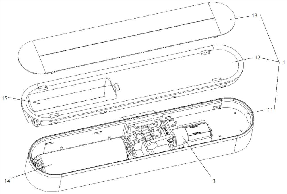
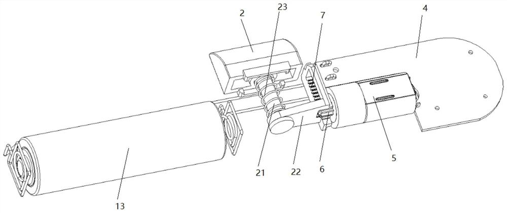
[0021] like figure 1 and figure 2 The driving mechanism of an intelligent lock shown includes a lock body 1, a lock tongue 2 is arranged in the lock body 1, and the lock tongue 2 slides out of the lock body 1, and a driving mechanism 3 arranged in the lock body 1 is also included. , the inner end of the deadbolt 2 is fixedly provided with a limit rod 21, and a connecting rod 22 is slidably sleeved on the limit rod 21, and the connecting rod 22 is connected with the limit rod 21 by a spring 23, and the driving mechanism 3 by circuit board 4, motor 5, reduction gear 6, rack 7, described circuit bo...


PUM


Abstract

The invention discloses an intelligent lock driving mechanism. A linting rod is fixedly arranged at the inner side end of a spring bolt, and the limiting rod is slidably sleeved with a connecting rod.The connecting rod and the limiting rod are connected through a spring, and the driving mechanism is composed of a circuit board, a motor, a reduction gear and a rack. The circuit board is electrically connected with the motor, the rack is fixed to the end of the connecting rod, the two ends of the rack correspond to the inner wall of a lock body, the reduction gear is engaged with the rack, andthe reduction gear is driven by the motor to rotate. The intelligent lock driving mechanism is compact in structure, low in cost, easy to assemble and high in applicability.

Description

technical field [0001] The invention relates to the field of intelligent locks, in particular to an intelligent lock driving mechanism. Background technique [0002] In recent years, smart cabinet locks have gradually emerged, and are widely used because they can be unlocked through mobile devices or biometrics without carrying a key. [0003] In addition to smart door locks, smart locks still include small smart lock products such as cabinet locks, U-shaped locks, and padlocks. Not suitable for small smart lock products. [0004] In addition, because the small smart lock is small in size and delicate in assembly, it is more prone to errors in the production process, so a driving mechanism with a compact structure, low cost, and simple enough assembly is very much needed. Contents of the invention [0005] (1) Technical problems to be solved [0006] In order to overcome the deficiencies of the prior art, an intelligent lock driving mechanism is proposed to solve the pr...

Claims


Application Information

Patent Timeline
IPC IPC(8): E05B47/00
CPCE05B47/0012E05B2047/002
Inventor 孙景鑫
Owner 西安易锁宝电子科技有限公司
Why Eureka
Try Eureka