

Medical soft ointment curing and stacking integrated drying and conveying device
A conveying device and an integrated technology, which are applied in the field of ointment curing and stacking integrated drying conveying devices, can solve the problems of lack of automatic stacking, inconvenience of automatic return of materials, unfavorable medicine drying and preparation, etc.
- Summary
- Abstract
- Description
- Claims
- Application Information
AI Technical Summary
Problems solved by technology
Method used
Image

Examples
Embodiment Construction
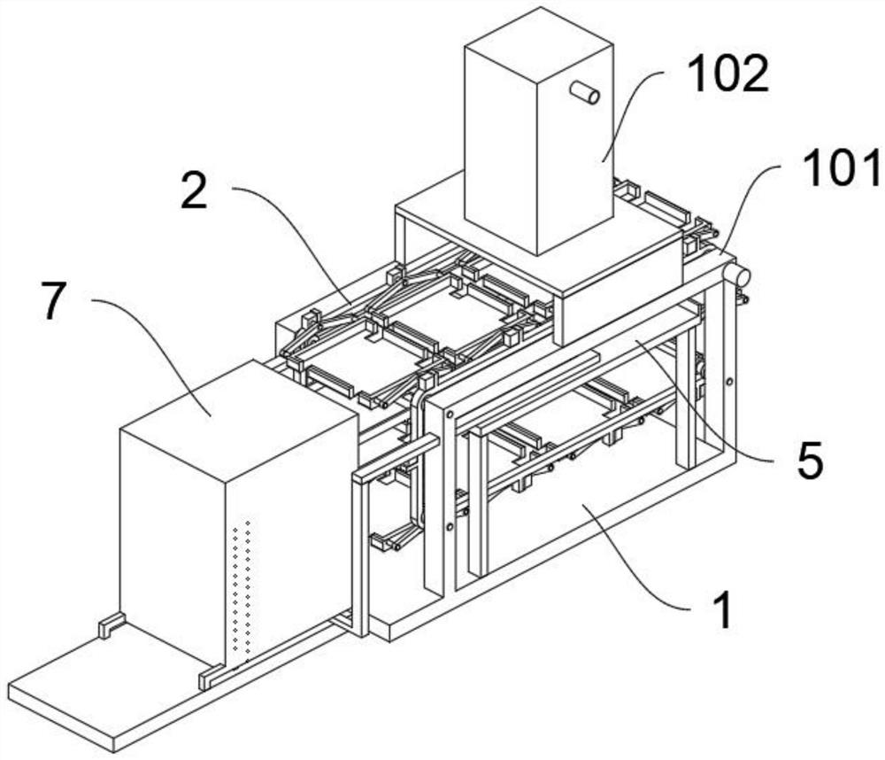
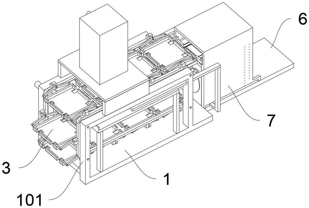
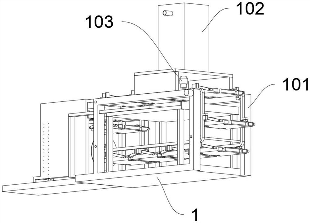
[0032] The following will clearly and completely describe the technical solutions in the embodiments of the present invention with reference to the accompanying drawings in the embodiments of the present invention. Obviously, the described embodiments are only some, not all, embodiments of the present invention.
[0033] see Figure 1 to Figure 9, an embodiment provided by the present invention: an integrated drying and conveying device based on medical ointment curing and stacking, including a base 1; Two groups of frames 101 are integrally arranged on both sides of the top of the frame 101; the drug storehouse 102 is installed by setting a frame structure between the top of the frame 101; Solenoid valve 103; the inner side of frame 101 is provided with conveyor belt 2, and the outer side of the roller of conveyor belt 2 is provided with motor; the outer side of conveyor belt 2 is uniformly provided with clamp structure, and the clamp structure outside conveyor belt One side...
PUM
 Abstract
Description
Claims
Application Information