Temperature compensation method and device of optical fiber gyroscope

A technology of fiber optic gyroscope and temperature compensation, which is applied in the field of navigation instruments and can solve problems such as the non-linearity of Shupe coefficients

Active Publication Date: 2020-10-30
北京思卓博瑞科技有限公司
View PDF8 Cites 4 Cited by
  • Summary
  • Abstract
  • Description
  • Claims
  • Application Information

AI Technical Summary

Problems solved by technology

[0005] One of the purposes of the present invention is to propose a temperature compensation method and device for an optical fiber gyroscope, which solves the technical problem of non-linearity of the Shupe coefficient of the high-precision optical fiber gyroscope in the prior art

Method used


Image

  • Temperature compensation method and device of optical fiber gyroscope
  • Temperature compensation method and device of optical fiber gyroscope
  • Temperature compensation method and device of optical fiber gyroscope

Examples


Embodiment Construction

[0042] In order to make the purpose, technical solution and advantages of the present invention clearer, the technical solution of the present invention will be described in detail below. Apparently, the described embodiments are only some of the embodiments of the present invention, but not all of them. Based on the embodiments of the present invention, all other implementations obtained by persons of ordinary skill in the art without making creative efforts fall within the protection scope of the present invention.

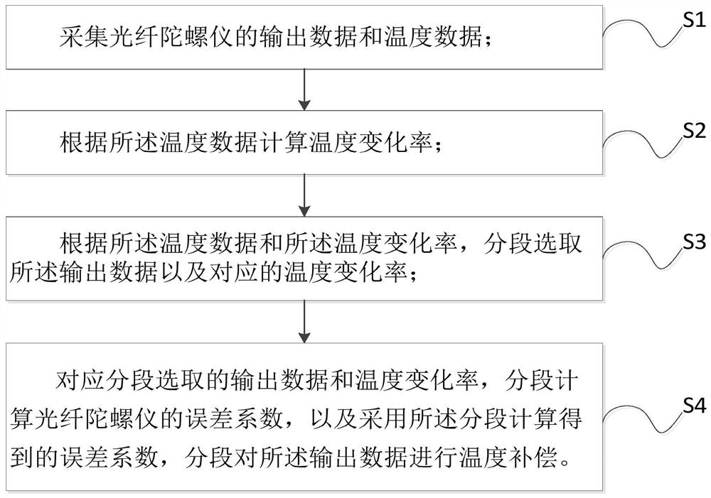
[0043] see figure 1 , the present invention is a kind of temperature compensation method of fiber optic gyroscope, it comprises:

[0044] S1: collect the output data and temperature data of the fiber optic gyroscope;

[0045] S2: Calculate the temperature change rate according to the temperature data;

[0046] S3: According to the temperature data and the temperature change rate, select the output data and the corresponding temperature change rate in sections...


PUM


Abstract

The invention provides a temperature compensation method and device for an optical fiber gyroscope, relates to the technical field of navigation instruments, and mainly solves the technical problem ofShupe coefficient nonlinearity of a high-precision optical fiber gyroscope. The method comprises the following steps: acquiring output data and temperature data of an optical fiber gyroscope; calculating a temperature change rate according to the temperature data; according to the temperature data and the temperature change rate, the output data and the corresponding temperature change rate are selected in a segmented mode; according to the output data and the temperature change rate which are selected in a segmented mode, error coefficients of the optical fiber gyroscope are calculated in asegmented mode, and temperature compensation is conducted on the output data in a segmented mode through the error coefficients obtained through segmented calculation. According to the invention, themeasurement precision of the fiber-optic gyroscope is improved, the nonlinear problem of the Shupe coefficient of the fiber-optic gyroscope is solved, and the practicability of the fiber-optic gyroscope is guaranteed.

Description

technical field [0001] The invention relates to the technical field of navigation instruments, in particular to a temperature compensation method and device for an optical fiber gyroscope. Background technique [0002] When the temperature of the fiber optic gyroscope changes, the zero bias will change. This is a "bottleneck" problem that has been widely concerned in the development of fiber optic gyroscope technology. When the temperature changes, the two beams of interfering light in the fiber optic ring will produce a non-reciprocal phase shift, which will change the zero bias of the gyroscope and greatly reduce the accuracy of the gyroscope. In the early 1980s, the American scholar D.M.Shupe explained this problem theoretically, so this error is called the Shupe effect error. After that, the optical fiber ring was made by winding symmetrically from the midpoint of the optical fiber length, which largely solved the non-reciprocal phase shift caused by temperature changes...

Claims


Application Information

Patent Timeline
Patent Type & Authority Applications(China)
IPC IPC(8): G01C25/00G01C19/72
CPCG01C25/005G01C19/72
Inventor 黄忠伟
Owner 北京思卓博瑞科技有限公司
Why Eureka
Try Eureka