Display device with flexible display

a display device and flexible technology, applied in the field of display devices with flexible displays, can solve the problems of difficult use of closing means of wrap-type display devices, deformation of frame portions when opening devices, and user unfriendly, and achieve the effect of small force and good mechanical compensation of supporting frames

Inactive Publication Date: 2013-07-18
SAMSUNG ELECTRONICS CO LTD
View PDF12 Cites 61 Cited by
  • Summary
  • Abstract
  • Description
  • Claims
  • Application Information

AI Technical Summary

Benefits of technology

[0010]According to another preferred embodiment of the invention said first locking part is connected by a ball hinge with the second end of the support frame. The ball hinge enables that the locking part can relative freely move in its connection with the second end of the support frame to find a position where the magnetic field of the magnet is coupled most optimal with its static counterpart (metal or magnet). The ball hinge also enables a good compensation for support frame mechanical inaccuracies resulting e.g. from assembly or wear.

Problems solved by technology

In the storage position the support frame of this ‘wrap’ type display is closed and locked by mechanical means, requiring a special handling which in practice, in combination with the handling for opening, is user unfriendly.
The use of closing means for a ‘wrap’ type display device applying magnetic force is difficult because the device design is very lightweight and flexible resulting in deformation of the frame portions when opening the device.
Another problem is the exact position and angle of the magnet that is required for an optimal closing force.
The use of a stronger magnet to compensate for less accuracy is not an option since this could result in the magnet erasing bank cards when they are close to the display device.

Method used


Image

  • Display device with flexible display
  • Display device with flexible display
  • Display device with flexible display

Examples


second embodiment

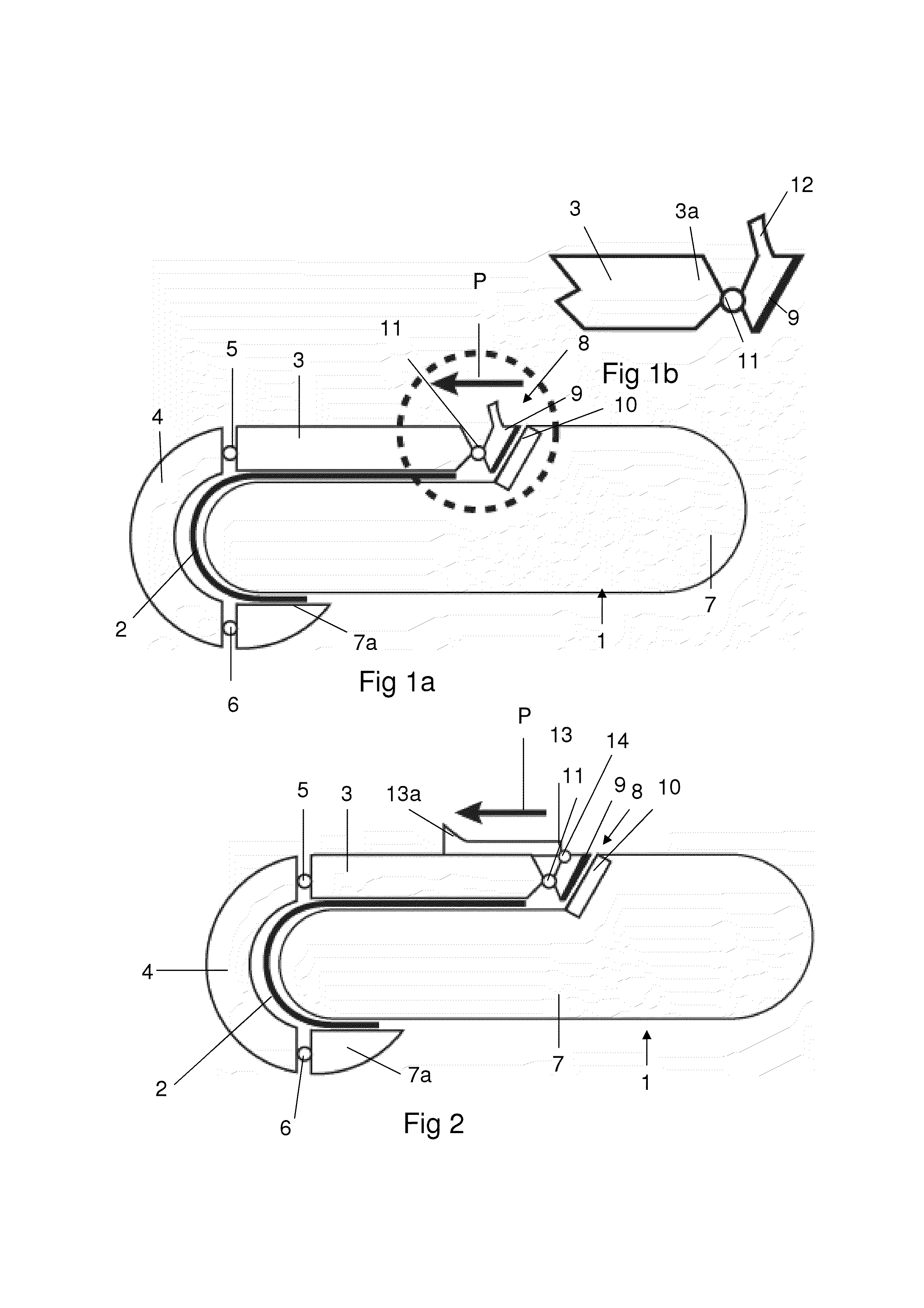
[0025]the display device 1 shown in FIG. 2 is also a ‘wrap’ type device. Parts that correspond with the embodiment of FIG. 1 are indicated by the same reference numerals. In this embodiment the unlocking member comprises a slider 13 which is movably connected to the first locking part 9 by a pivot 14, extending substantially parallel to the pivot axis 11 in the connection of the part 9 with the second end 3a of the support frame. For unlocking the second end 3a from the device body 7 the slider 13 is movably guided at the frame portion 3 substantially in the length direction of the device body 7 (direction of arrow P). Due to this movement the slider 13 rotates the part 9 around the pivot axis 11 in anti-clockwise direction and causes the part 9 to come free from the part 10 thereby unlocking the second end 3a from the device body 7. The slider 13 is provided with a hook portion 13a enabling an easy manual unlocking. Preferably the slider 13 is spring loaded and moves after unlockin...

third embodiment

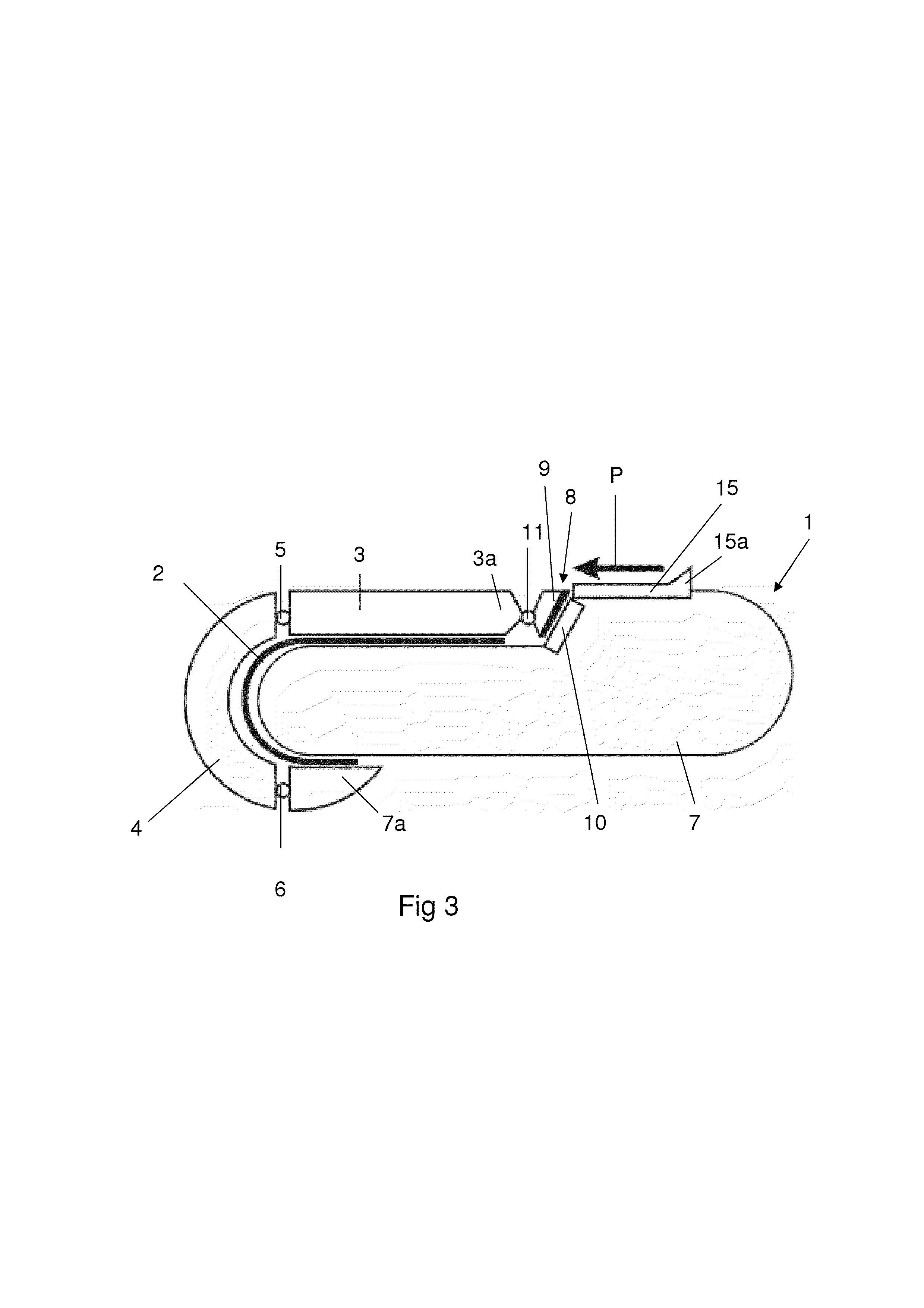
[0026]Also the display device 1 shown in FIG. 3 is a ‘wrap’ type device. Parts that correspond with the embodiments of FIGS. 1 and 2 are indicated by the same reference numerals. In this embodiment the unlocking member comprises a slider 15 which is movable guided at the upper side of the device body 7 substantially in the length direction of the device body 7 (direction of arrow P). An upper corner of the part 9 is located in the path of movement of the slider 15. Due to this movement the slider 15 abuts the upper corner of the part 9, causing the part 9 to rotate around the pivot axis 11 in anti-clockwise direction, the part 9 coming free from the part 10 thereby unlocking the support frame from the device body 7. The slider 15 is provided with a hook portion 15a enabling an easy manual unlocking. Preferably the slider 15 is spring loaded and moves after unlocking and opening of the support frame back to its original position on the device body 7.

fourth embodiment

[0027]the display device 1 shown in FIGS. 4a and 4b is also a ‘wrap’ type device. Parts that correspond with the embodiments of FIGS. 1, 2 and 3 are indicated by the same reference numerals. In this embodiment the first locking part is a U-shaped rim 16, neighboring a plate shaped end portion 17 of the support frame comprising the second support frame end portion. Both the U-shaped rim 16 and the plate shaped end portion 17 are connected via the hinge part 5 with the frame portion 4. The plate shaped end portion 17 supports a part of the flexible display 2 and substitutes the function of the frame portion 3 in the preceding embodiments. The U-shaped rim 16 is of a material, such as glass fiber reinforced plastics or aluminum, movable connected with the plate shaped end portion 17 via arms 18 extending substantially parallel to the hinges in the hinge parts 5,6. Important for the invention is that the rim 16 is substantially more stiff than the plate shaped end portion 17. Preferably...


PUM


Abstract

The invention relates to a display device (1) with a device body (7), a continuous flexible display (2) and an elongated support frame configured to support the flexible display, being provided with mutually movable connected frame portions (3,4) and being hingeably connected at a first end (7a) with the device body (7) between a closed configuration for fixing the flexible display in a wrapped storage position and an open configuration. The display device (1) comprises magnetic closing means (8) being provided with a first locking part (9) being movable connected with a major part of the support frame and being capable for magnetically locking of a second end (3a) of the support frame in the closed configuration to the device body (7) and being provided with at least one unlocking member (12) enabling a manual unlocking of said second end (3a) from the device body (7).

Description

FIELD OF INVENTION[0001]The present invention generally relates to display devices with a flexible display. The present invention specifically relates to display devices of the kind comprising a device body, a continuous flexible display, an elongated support frame configured to support the flexible display, being provided with mutually movable connected frame portions and being hingeably connected at a first end to the device body between a closed configuration for fixing the flexible display in a wrapped storage position with respect to the device body and an open configuration for fixing the flexible display in an unwrapped open position,DESCRIPTION OF PRIOR ART[0002]Mobile display devices, such as mobile phones or e-readers, which make use of flexible displays have in their storage position a compact state, for instance for transportation, previewing or phone calls. In the open position they are in a reading / viewing state with the continuous flexible display in extended position...

Claims


Application Information

Patent Timeline
Patent Type & Authority Applications(United States)
IPC IPC(8): B65D1/00
CPCG06F1/1652B65D1/00G06F1/1679
Inventor HAMERS, JOHANNES CORNELIS ADRIAANWALTERS, MICHAELVAN DIJK, ROBERT
Owner SAMSUNG ELECTRONICS CO LTD
Why Eureka
Try Eureka