Method, device and system for determining signal arrival angle
A technology of angle of arrival and signal, which is applied in the field of communication, can solve problems such as difficulty in forming a multi-level codebook antenna gain pattern that meets the requirements, beam width with limited resolution capability, and high power consumption of radio frequency links, etc., to achieve fast and accurate beam Effects on training performance, fast beam training, improved reliability and stability
- Summary
- Abstract
- Description
- Claims
- Application Information
AI Technical Summary
Problems solved by technology
Method used
Image
Examples
example 1
[0209] Example 1), the sending device and the receiving device communicate using frequency division multiple access (frequency division multiple access, FDMA) technology or orthogonal frequency division multiple access (Orthogonal Frequency Division Multiple Access, OFDMA) technology.
[0210] In example 1), the reference signal resources configured by the receiving device for the sending device are orthogonal to the reference signal resources configured by the receiving device for other sending devices in the frequency domain. That is, the receiving device configures time-frequency resources for multiple sending devices including the sending device, and different sending devices occupy different subcarriers or carriers in the frequency domain, and different sending devices can occupy the same subcarrier or carrier in the time domain. OFDM symbols or FDM symbols.
[0211] In example 1), multiple reference signals occupy one OFDM symbol and J subcarriers each time.
[0212] Th...
example 2
[0216] Example 2), the sending device and the receiving device use carrier sense multiple access (Carrier Sense Multiple Access, CSMA) technology for communication or time division multiple access (Time Division Multiple Access, TDMA) technology for communication.
[0217] In example 2), the time domain of the reference signal resources configured by the receiving device for the sending device is different from the time domain of the reference signal resources configured by the receiving device for other sending devices. That is, the reference signal resources configured by the receiving device for different sending devices are allocated to different time intervals, so that multiple different sending devices can use their respective configured reference signal resources to send reference signals to the receiving device in different time intervals . Therefore, multiple different sending devices can perform beam training in series without conflicting with each other. It should ...
example 3
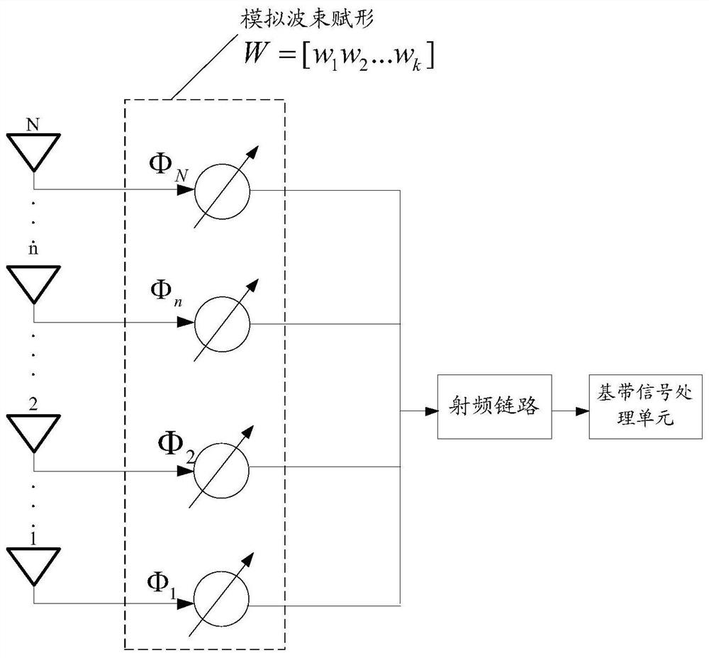
[0221] Example 3), the array antenna architecture of the sending device and the receiving device is a hybrid beamforming architecture. When the array antenna architecture is an analog beamforming architecture, the system multiple access method considers two situations: OFDMA or (FDMA), CSMA (or TDMA), the difference between these two multiple access methods is whether multiple sending devices can be simultaneously AoA estimate. Similarly, when the array antenna architecture is a hybrid beamforming architecture, the same two situations exist in the multiple access mode of the system. Example 3) is only described in conjunction with the OFDMA system.
[0222] The hybrid beamforming architecture can form multiple beams with different directions at the same time, further reducing the overhead of beam switching. The number of beams with different directions is represented by I. Different terminals use different subcarriers to send uplink reference signals at the same time, so tha...
PUM
 Abstract
Description
Claims
Application Information
 - R&D
- Intellectual Property
- Life Sciences
- Materials
- Tech Scout
- Unparalleled Data Quality
- Higher Quality Content
- 60% Fewer Hallucinations
Browse by: Latest US Patents, China's latest patents, Technical Efficacy Thesaurus, Application Domain, Technology Topic, Popular Technical Reports.
© 2025 PatSnap. All rights reserved.Legal|Privacy policy|Modern Slavery Act Transparency Statement|Sitemap|About US| Contact US: help@patsnap.com


