Tow hook installation structure

A technology of installation structure and tow hook, which is applied in the direction of vehicle components, transportation and packaging, traction connector, etc. It can solve the problems of position deviation, time-consuming and labor-intensive, affecting the screw-in of the tow hook, etc.

Active Publication Date: 2021-11-02
CHERY AUTOMOBILE CO LTD
View PDF10 Cites 0 Cited by
  • Summary
  • Abstract
  • Description
  • Claims
  • Application Information

AI Technical Summary

Problems solved by technology

Yet in this application, there are front and rear nut seats, which need to be threaded with the front and rear two nut seats when screwed into the tow hook. When the tow hook is screwed into the front nut seat, it continues to screw forward. When the threaded end of the hook reaches the rear nut seat, it is easy to produce a position deviation. At this time, idle rotation will occur on the rear nut seat. During the rotation of the tow hook, the tow hook extends into the front nut seat and its end fails to rotate in time. Insert the rear nut seat, so that the end of the tow hook will press against the rear nut seat. It is necessary to repeatedly unscrew the tow hook and screw it in to align with the rear nut seat. When the rear nut seat is pressed, the position of the rear nut seat will be shifted, which will further affect the screwing in of the tow hook

Method used


Image

  • Tow hook installation structure
  • Tow hook installation structure
  • Tow hook installation structure

Examples


Embodiment 1

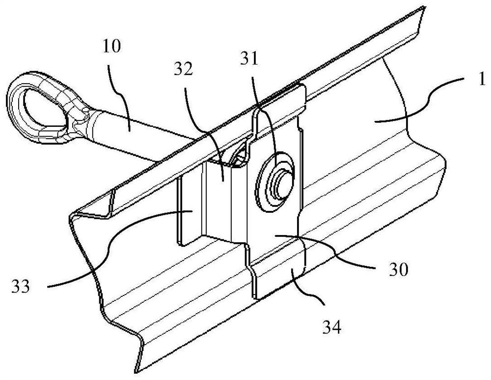
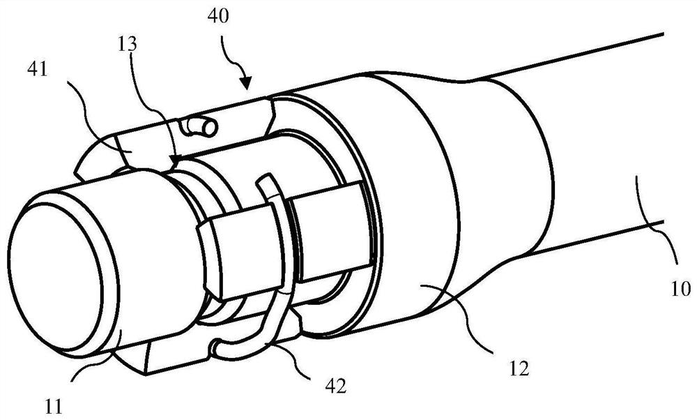
[0017] Embodiment 1: The expansion unit 40 includes at least two shoe-shaped blocks 41 that are evenly spaced circumferentially in front of the threaded section 11 of the tow bar 10 , and a C-shaped clamp spring 42 is provided at the rear of the outer middle of the shoe-shaped blocks 41 Constraint tile block 41 abuts on tow bar 10, and tow bar 10 is provided with outwardly protruding step shaft 12 adjacent to the front end of tile block 41. After threaded section 11 of tow bar 10 is screwed into nut seat 31, tile block 41 is The nut seat 31 and the step shaft 12 are squeezed to drive the shoe block 41 around its rear end to form a swing away from the tow bar 10 at the front end, and the front end of the shoe block 41 far away from the tow bar 10 abuts against the groove of the front anti-collision beam 1 The bottom and it form a position-limiting fit that limits the forward displacement of the tow bar 10 relative to the front anti-collision beam 1 . In the above scheme, at lea...

Embodiment 2

[0022] Embodiment 2: The expansion unit 40 includes an elastic sleeve 43 provided in front of the threaded section 11 of the tow bar 10 , the tow bar 10 is provided with an outwardly protruding stepped shaft 12 adjacent to the front end of the elastic sleeve 43 , and the threaded section 11 of the tow bar 10 After being screwed into the nut seat 31, the elastic sleeve 43 is squeezed between the nut seat 31 and the step shaft 12 to drive the front end of the elastic sleeve 43 to expand and fit on the step shaft 12, and the front end of the elastic sleeve 43 on the step shaft 12 is against the front end. The bottom of the groove of the anti-collision beam 1, or the elastic sleeve 43 on the step shaft 12 is embedded by the hole edge of the through hole 20 and the front anti-collision beam 1 constitutes a limit fit to limit the forward displacement of the tow bar 10 relative to the front anti-collision beam 1 . In the above solution, the extrusion of the nut seat 31 and the steppe...


PUM


Abstract

The invention provides a tow hook installation structure, which comprises a through hole formed at the bottom of the groove of the front anti-collision beam for the tow bar to pass through, a nut seat is arranged behind the through hole, and a threaded section of the tow bar in the vehicle length direction is provided. An expansion unit is arranged immediately in front of the unit. After the threaded section of the trailer rod is screwed into the nut seat, the rear end of the expansion unit and the nut seat are squeezed to drive the front end of the expansion unit to open, and the front end of the expansion unit is opened. The bottom of the groove constitutes a limit fit for restricting the forward displacement of the tow bar relative to the front crash beam. The common threaded pipe installation structure is cancelled, so as to prevent the excessively long rigid threaded pipe structure from occupying the compression space of the energy-absorbing box, and at the same time, a nut seat is reduced on the basis of the solution of the applicant's previous application, which makes the trailer When the hook is installed, only one nut seat is required to avoid mutual interference when multiple nut seats are installed together.

Description

technical field [0001] The invention relates to the field of auto parts, in particular to a tow hook installation structure. Background technique [0002] The tow hook is the trailer and towing device of the car. Many brands of cars have a tow hook when they leave the factory. The car tow hook has become a must-have part of the car. [0003] The applicant's prior application publication number is CN110962513A, which discloses a trailer coupler nut box, which cancels the common nut tube structure by setting the front and rear two nut seats, so as to avoid the threaded tube arranged in front of the energy absorbing box. Occupying the compression space of the energy-absorbing box ensures that the energy-absorbing box can fully compress and absorb energy when the vehicle is hit. Yet in this application, there are front and rear nut seats, which need to be threaded with the front and rear two nut seats when screwed into the tow hook. When the tow hook is screwed into the front n...

Claims


Application Information

Patent Timeline
Patent Type & Authority Patents(China)
IPC IPC(8): B60D1/48B60D1/56B60D1/04
CPCB60D1/04B60D1/48B60D1/56
Inventor 牛宝忠杨克璧黄瑛孙晓燕张正
Owner CHERY AUTOMOBILE CO LTD
Why Eureka
Try Eureka