Unmanned aerial vehicle panoramic image real-time monitoring structure and unmanned aerial vehicle

A panoramic image, real-time monitoring technology, applied in mechanical equipment, aircraft parts, spring/shock absorber design features, etc., can solve the problems of occlusion, shooting blind spots, poor use effect, etc., achieve good picture overlap, increase photography Height, good splicing effect

Pending Publication Date: 2020-11-03
MEIZHOU POWER SUPPLY BUREAU OF GUANGDONG POWER GRID CORP
View PDF8 Cites 2 Cited by
  • Summary
  • Abstract
  • Description
  • Claims
  • Application Information

AI Technical Summary

Problems solved by technology

However, in the actual operation of special UAVs, it was found that most of the multi-rotor UAV products with large load capacity on the market lack the function of real-time monitoring of the surrounding environment and operation process of UAVs during the operation process.
Moreover, since these multi-rotor UAVs for special operations need to complete high-altitude operations, the operating platform is generally mounted on the bottom of the UAV, which makes it impossible to install other equipment on the bottom of the UAV.
[0003] Although some drones use the method of setting cameras around the fuselage to take pictures and monitor the environment around the drone, this camera setting method is easily blocked by the fuselage or wings of the drone, resulting in blind spots for shooting. Poor use

Method used


Image

  • Unmanned aerial vehicle panoramic image real-time monitoring structure and unmanned aerial vehicle
  • Unmanned aerial vehicle panoramic image real-time monitoring structure and unmanned aerial vehicle
  • Unmanned aerial vehicle panoramic image real-time monitoring structure and unmanned aerial vehicle

Examples


Embodiment 1

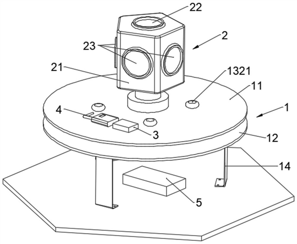
[0037] Such as Figure 1-2 As shown, the present embodiment provides a real-time monitoring structure for unmanned aerial vehicle panoramic images, including: a shock absorber 1, a panoramic camera device 2, a data processing device 3, a wireless image transmission device 4 and a power supply 5, wherein the shock absorber 1 Can be fixedly installed on the top of the drone; the panoramic camera device 2 is fixedly installed on the top of the shock absorber 1, and can collect panoramic images around the drone; the panoramic camera device 2 includes a camera connector 21, a first camera device 22 And five second imaging devices 23, the camera connector 21 is a regular pentagonal cylinder structure, the first imaging device 22 is fixed on the top of the camera connector 21, and the second camera device 23 is respectively arranged on five of the camera connectors 21. On the side, the images taken by two adjacent second camera devices 23 overlap, and the images taken by each second ...

Embodiment 2

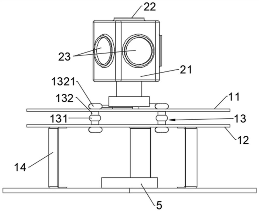
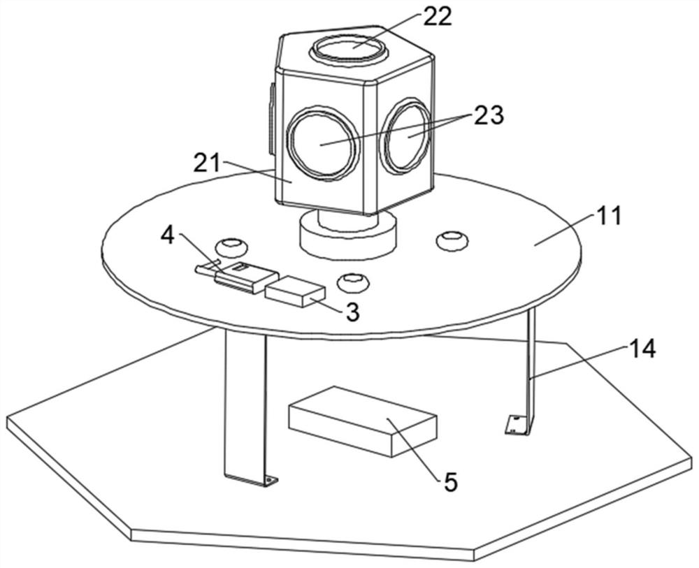
[0052] Such as Figure 3-4 As shown, the present embodiment is to provide a real-time monitoring structure for the panoramic image of the drone. The difference between the real-time monitoring structure of the panoramic image of the drone of the present embodiment and Embodiment 1 is that the shock-absorbing seat 1 includes a first pan-tilt support plate 11 and at least three supporting feet 14, panoramic camera device 2 is fixed on the top center of the first cloud platform support plate 11, and supporting foot 14 is all fixed on the bottom of the first cloud platform supporting plate 11, and supporting foot 14 is metal elastic member, and then makes supporting foot 14 has the effect of cushioning and shock absorption; when the UAV lands, the impact force is relatively large, and the support foot 14 is subjected to a small amount of bending deformation, which then plays a buffering effect and protects the monitoring structure from being damaged due to strong vibration.

[005...


PUM


Abstract

The invention discloses an unmanned aerial vehicle panoramic image real-time monitoring structure, and belongs to the technical field of unmanned aerial vehicle real-time monitoring. The invention provides the unmanned aerial vehicle panoramic image real-time monitoring structure, and the structure comprises a damping seat and a panoramic camera device; the panoramic camera device is fixedly installed at the top of the damping seat, and the panoramic camera device can collect panoramic images around an unmanned aerial vehicle; the panoramic camera shooting device comprises a camera connectingpart, a first camera shooting device and five second camera shooting devices, wherein the images shot by every two adjacent second camera shooting devices are overlapped, and an image shot by each second camera shooting device is overlapped with an image shot by the first camera shooting device. The panoramic camera device is arranged at the top of the unmanned aerial vehicle through the damping seat, so the panoramic image real-time monitoring function of the unmanned aerial vehicle is realized, and the operation capability of the unmanned aerial vehicle is not influenced; moreover, the damping seat increases the photographing height of the panoramic photographing device, and improves the quality of images photographed by the camera.

Description

technical field [0001] The invention relates to the technical field of real-time monitoring of drones, in particular to a real-time monitoring structure of panoramic images of drones and the drone. Background technique [0002] In recent years, the development and rise of drone technology has been widely used and recognized in many industries such as energy, agriculture, forestry, and fire protection. And with the continuous innovation of UAV technology, UAVs for high-altitude special operations are showing a diversified development trend, which has greatly improved the efficiency of high-altitude operations and brought obvious social and economic benefits. However, in the actual operation of special UAVs, it was found that most of the multi-rotor UAV products with large load capacity on the market lack the function of real-time monitoring of the surrounding environment and operation process of UAVs during the operation process. Moreover, since these multi-rotor UAVs for sp...

Claims


Application Information

Patent Timeline
Patent Type & Authority Applications(China)
IPC IPC(8): B64D47/08F16F15/08
CPCB64D47/08F16F15/085F16F2230/14
Inventor 袁徐刘远君徐海松谢文敏曾文其梅冬芳钟梓熙
Owner MEIZHOU POWER SUPPLY BUREAU OF GUANGDONG POWER GRID CORP
Why Eureka
Try Eureka