Partially prefabricated ground connection wall guide wall under underground facilities and construction method

A technology for underground facilities and ground-to-ground walls, which is applied in sheet pile walls, infrastructure engineering, construction, etc., can solve the problems that reinforced concrete guide walls cannot be constructed, and the construction of ground-to-ground walls is difficult, and achieves simple construction and fast connection speed. , the effect of large node stiffness

Active Publication Date: 2021-06-22
SHANDONG UNIV
View PDF0 Cites 0 Cited by
  • Summary
  • Abstract
  • Description
  • Claims
  • Application Information

AI Technical Summary

Problems solved by technology

[0003] At present, the guide wall of the ground connection wall usually adopts a reinforced concrete guide wall, but the inventor found that due to the local basement facilities, the reinforced concrete guide wall cannot be constructed, which brings difficulties to the construction of the entire ground connection wall

Method used


Image

  • Partially prefabricated ground connection wall guide wall under underground facilities and construction method
  • Partially prefabricated ground connection wall guide wall under underground facilities and construction method
  • Partially prefabricated ground connection wall guide wall under underground facilities and construction method

Examples


Embodiment 1

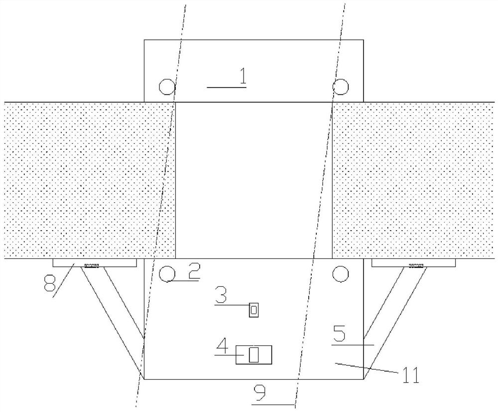
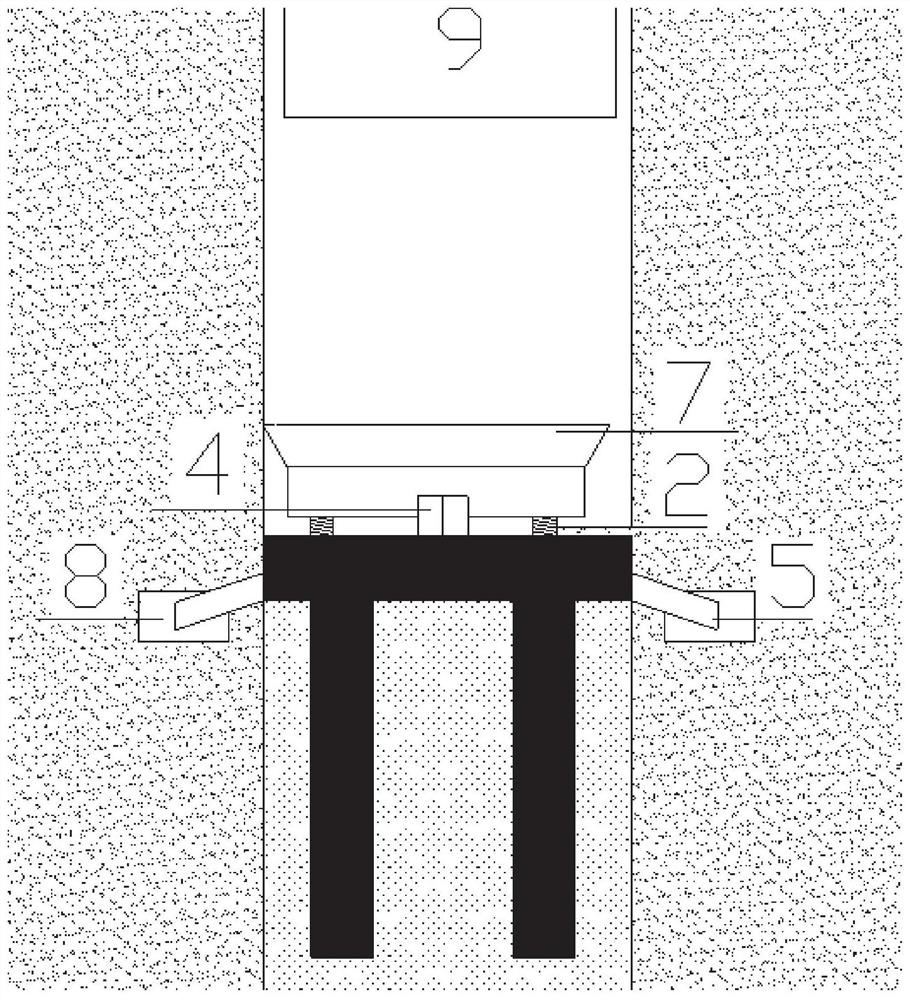
[0034] This embodiment provides a partially prefabricated ground connecting wall guide wall under the underground facility, which is arranged below the cable trench 9, and the trench is constructed below the cable trench 9. The cable trench 9 is used as an obstacle and needs to be dragged by underpinning. Such as figure 1 with figure 2 As shown, it includes a first guide wall 1 and a second guide wall 11 that are oppositely arranged, and the first guide wall 1 and the second guide wall 11 are respectively arranged on both sides of the trench.

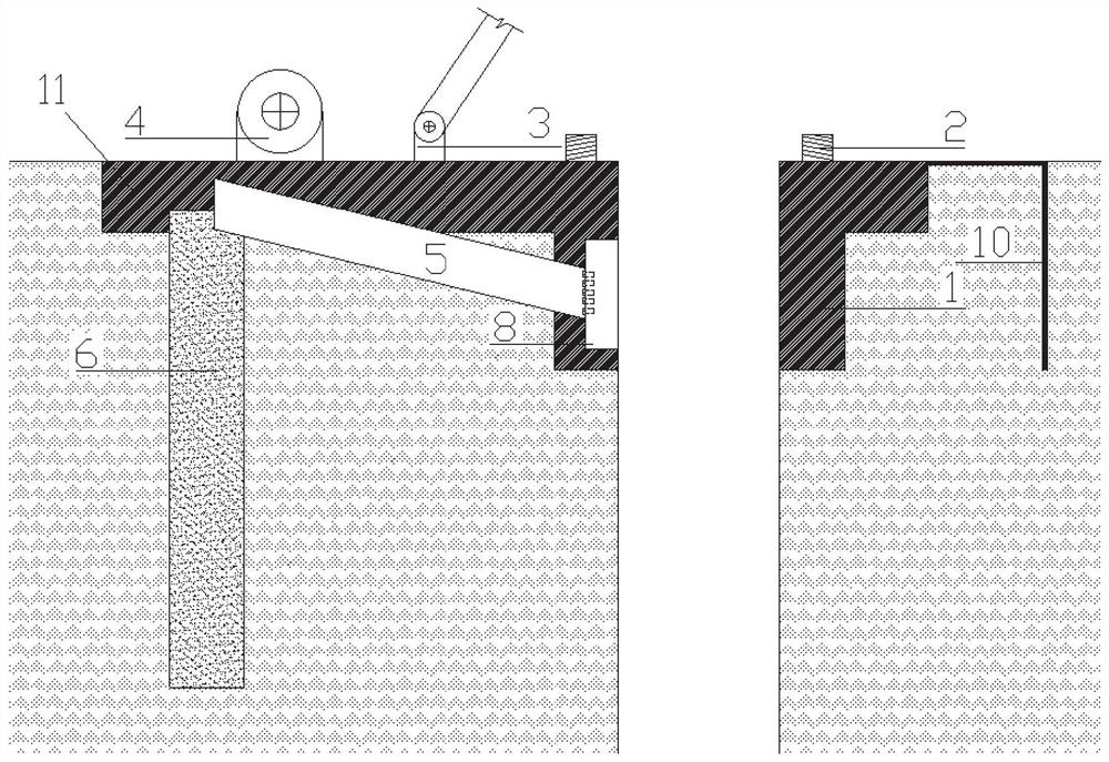
[0035] One end of the second guide wall 11 is connected to the surrounding purlin 8, and the other end is connected to a plurality of uplift piles 6, and the uplift piles 6 are arranged vertically along the interior of the soil. Further, the uplift pile 6 is a reinforced concrete uplift pile. The pullout pile 6 is connected to the purlin 8 through the pullout pipe 5, and the pullout pipe 5 is steel.

[0036] Such as figure 2 with ...

Embodiment 2

[0045] This embodiment provides a construction method for partially prefabricated ground connecting walls and guide walls under underground facilities, which is constructed below the cable trench 9, including:

[0046] Step 1: Preparatory work before installing the guide wall:

[0047] (1) Pre-buried the fence 8 during the construction of the ground connection wall, or installed the fence 8 on the existing ground connection wall 9 . The side of the purlin 8 is left with a connection node for connecting the pullout pipe 5, and this connection node provides a large pulling force for the second guide wall 11 and subsequent operations to ensure the safety of the second guide wall 11.

[0048] (2) The uplift pile 6 is constructed in the auxiliary foundation pit, and the main reinforcement is reserved on the ground surface to prepare for the connection of the second guide wall 11 in the later stage. Since the 6 pile tops of the uplift piles are located underground, and the constructi...


PUM


Abstract

The invention discloses a partially prefabricated ground connecting wall guide wall under an underground facility and a construction method thereof. The technical proposal is: a first guide wall and a second guide wall arranged opposite to each other, and the first guide wall is far away from the second guide wall A connecting plate is fixed at one end; one end of the second guide wall is connected to a purlin, and the other end is connected to a plurality of uplift piles; the purlin and the uplift pile are connected through a pullout pipe. The local prefabricated steel plate guide wall of the present invention can overcome the difficulties of the existing construction guide wall in a local special environment; the nodes have high rigidity, fast connection speed, easy installation and operation in the blocking space caused by the cable trench, and high construction efficiency.

Description

technical field [0001] The invention relates to the field of foundation pit engineering, in particular to a partially prefabricated ground connection wall guide wall under an underground facility and a construction method. Background technique [0002] The demand for underground space in modern buildings is increasing. Therefore, ground connection walls are used more and more in engineering. Among them, the ground connection wall guide wall is the first step in the construction of the ground connection wall. [0003] At present, the guide wall of the ground connection wall usually adopts a reinforced concrete guide wall, but the inventor found that due to the local basement facilities, the reinforced concrete guide wall cannot be constructed, which brings difficulties to the construction of the entire ground connection wall. Contents of the invention [0004] Aiming at the deficiencies in the prior art, the purpose of the present invention is to provide a local prefabrica...

Claims


Application Information

Patent Timeline
Patent Type & Authority Patents(China)
IPC IPC(8): E02D5/20
CPCE02D5/20
Inventor 李连祥苏日嘎拉图杨立亭李红波于克猛李伟同
Owner SHANDONG UNIV
Why Eureka
Try Eureka