Steel pipe and flange welding butt joint connection robot

A flange welding and robot technology, applied in welding equipment, auxiliary welding equipment, welding/cutting auxiliary equipment, etc., to meet the requirements of the degree of freedom, to facilitate welding and screwing, and to improve the degree of freedom

Active Publication Date: 2020-11-06
江苏昆仑光源材料有限公司
View PDF9 Cites 0 Cited by
  • Summary
  • Abstract
  • Description
  • Claims
  • Application Information

AI Technical Summary

Problems solved by technology

[0002] The connection between steel pipes mainly adopts flange connection. It is necessary to weld the flange on the steel pipe first, and then use bolts to connect the two flanges. This method is usually carried out manually. In order to receive manpower and speed up, the design is now A steel pipe flange welding butt joint robot, for example, Patent Application No. CN201020178168.9 discloses a steel pipe flange welding tool, which can assist steel pipe flanges in welding, but requires manual operation; for example, Patent No. CN201120108690.4 discloses a A steel pipe flange welding positioning device, the device can assist the steel pipe flange welding process, but still requires manual operation

Method used


Image

  • Steel pipe and flange welding butt joint connection robot
  • Steel pipe and flange welding butt joint connection robot
  • Steel pipe and flange welding butt joint connection robot

Examples


Embodiment Construction

[0028] The present invention will be further described below in conjunction with specific embodiments. The exemplary embodiments and descriptions of the present invention are used to explain the present invention, but not as a limitation to the present invention.

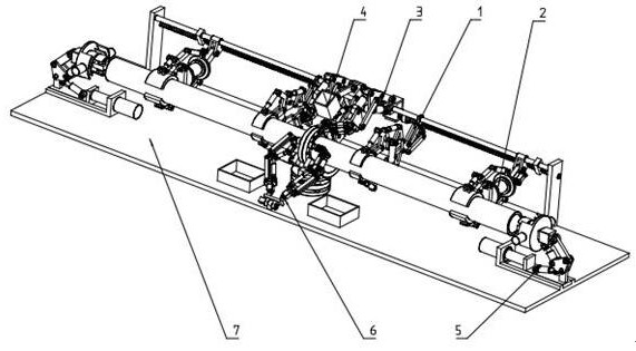
[0029] Such as figure 1 , figure 2 , image 3 , Figure 4 , Figure 5 , Figure 6 , Figure 7 , Figure 8 A steel pipe flange welding butt joint robot shown includes a main clamping part 1 , an auxiliary clamping part 2 , a welding part 3 , an auxiliary part 4 , a pipe transfer part 5 , a bolt screwing part 6 and a body part 7 .

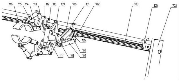
[0030] The main frame foundation 101 and the transmission screw rod 703 of the main clamping part 1 adopt screw transmission, and are slidably installed with the transmission guide rail 704. A stepping motor is fixedly installed on the main frame foundation 101, and the clamping screw rod 102 is fixedly installed on the stepping motor. , the clamping small block 103 is slidably ins...


PUM


Abstract

The invention discloses a steel pipe and flange welding butt joint connection robot. A main body of the steel pipe and flange welding butt joint connection robot is composed of a main clamping part, auxiliary clamping parts, a welding part, an auxiliary part, pipe rotation parts, a screw twisting part, a machine body part and the like. The main clamping part comprises a main frame base, an arrow plate, a main clamping jaw and the like. Each auxiliary clamping part comprises an auxiliary frame base, a jaw plate and the like. The welding part comprises an upper single rod, a welding rotation block and the like. The auxiliary part comprises a fixed clamp, a movable clamp and the like. Each pipe rotation part comprises a telescopic plate frame, an upper clamping block, a lower clamping block and the like. The screw twisting part comprises a basic twisting block, a fork rod and the like. The machine body part comprises a bottom plate, a lower clamping disc and the like. During use, a steelpipe is clamped and fixed through the main clamping part and the auxiliary clamping parts, flanges are placed on the main body part and fixed through the auxiliary part, then the steel pipe and the flanges are welded through the welding part and the pipe rotation parts, and after welding is completed, the two flanges are connected through the screw twisting part.

Description

technical field [0001] The invention relates to the technical field of steel processing, in particular to the technical field of a steel pipe flange welding butt joint robot. Background technique [0002] The connection between steel pipes mainly adopts flange connection. It is necessary to weld the flange on the steel pipe first, and then use bolts to connect the two flanges. This method is usually carried out manually. In order to receive manpower and speed up, the design is now A steel pipe flange welding butt joint robot, for example, Patent Application No. CN201020178168.9 discloses a steel pipe flange welding tool, which can assist steel pipe flanges in welding, but requires manual operation; for example, Patent No. CN201120108690.4 discloses a A steel pipe flange welding positioning device, the device can assist the steel pipe flange welding process, but still requires manual operation. Contents of the invention [0003] In view of the above problems, the present i...

Claims


Application Information

Patent Timeline
Patent Type & Authority Applications(China)
IPC IPC(8): B23K37/053B23K37/04B23K37/02
CPCB23K37/0533B23K37/0538B23K37/0435B23K37/0252
Inventor 于跃明
Owner 江苏昆仑光源材料有限公司
Why Eureka
Try Eureka