Al technical title is built by PatSnap Al team. It summarizes the technical point description of the patent document.
A flange welding and robot technology, applied in welding equipment, auxiliary welding equipment, welding/cutting auxiliary equipment, etc., to achieve the effect of improving the degree of freedom, meeting the requirements of freedom, and convenient welding and screwing
Active Publication Date: 2021-12-10
江苏昆仑光源材料有限公司
View PDF9 Cites 0 Cited by
Summary
Abstract
Description
Claims
Application Information
AI Technical Summary
This helps you quickly interpret patents by identifying the three key elements:
Problems solved by technology
Method used
Benefits of technology
Problems solved by technology
[0002] The connection between steel pipes mainly adopts flange connection. It is necessary to weld the flange on the steel pipe first, and then use bolts to connect the two flanges. This method is usually carried out manually. In order to receive manpower and speed up, the design is now A steel pipe flange welding butt joint robot, for example, Patent Application No. CN201020178168.9 discloses a steel pipe flange welding tool, which can assist steel pipe flanges in welding, but requires manual operation; for example, Patent No. CN201120108690.4 discloses a A steel pipe flange welding positioning device, the device can assist the steel pipe flange welding process, but still requires manual operation
Method used
Image
Click on the blue label to locate the original text in one second.
Reading with bidirectional positioning of images and text.
Examples
Embodiment Construction
[0028] The present invention will be further described below in conjunction with the specific embodiments.
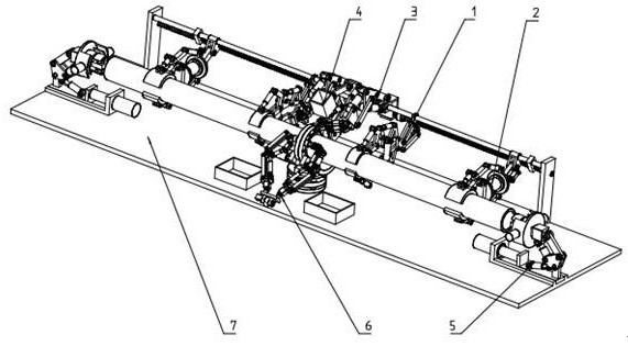
[0029] like figure 1 , figure 2 , image 3 , Figure 4 , Figure 5 , Image 6 , Figure 7 , Figure 8 A steel pipe flange welding a docking robot, including the main clamping portion 1, the sub-clamping portion 2, the welding portion 3, the auxiliary portion 4, the transfer portion 5, the screw bolt portion 6, and the body portion 7.
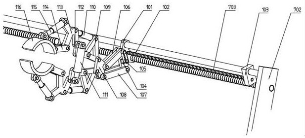
[0030] The main frame base 101 of the main clamping portion 1 and the drive rod 703 use a threaded transmission, sliding with the drive guide rail 704, and fixedly mounted a stepping motor on the main frame base 101, and holds the screw 102 fixed to the stepping motor. The clamping small block 103 is slidable with the drive guide rail 704, and the other end of the clamping rod 102 is rotated and the clamping small piece 103 is mounted, and the first step feeder 104 is fixedly mounted on the main frame base 101, holding the main rod 106 and the main...
PUM
Abstract
The invention discloses a steel pipe flange welding butt joint robot, the main body of which is composed of a main clamping part, an auxiliary clamping part, a welding part, an auxiliary part, a pipe transfer part, a bolt screwing part, a body part, etc.; the main clamping part includes: Main frame foundation, arrow plate, main jaw, etc.; auxiliary clamping part includes: sub-frame foundation, claw plate, etc.; welding part includes: upper single rod, welding rotary block, etc.; auxiliary part includes: fixed clip, movable clip, etc.; The rotating tube part includes: expansion plate frame, upper and lower clamping blocks, etc.; the bolt screwing part includes: basic screwing block, fork rod, etc.; the body part includes: bottom plate, lower clamping plate, etc.; The steel pipe is clamped and fixed by the part, the flange is placed on the main part, and fixed by the auxiliary part, and then the welding part and the transfer part are welded to the steel pipe and the flange. After the welding is completed, the two flanges are then screwed connect them.
Description
Technical field [0001] The present invention relates to the technical field of steel working, particularly to a steel flange welded butt robotics. Background technique [0002] The connection between the main pipe flange connection, the flanges need to be welded on the pipe, and then the bolts connecting the two flanges, this method is usually carried out manually, for liberating human and speed, is designed butt welding robot for a steel pipe flange, for example, Patent application No. CN201020178168.9 discloses a welded steel flange tooling, the apparatus may assist steel flange for welding, but requires manual operation; for example, Patent No. CN201120108690.4 discloses a welding of Pipe flange positioning apparatus, the apparatus may assist steel flange for welding, but still require manual operation. Inventive content [0003] For the above problems, the present invention provides a steel flange welded butt robot main body by the clamping portion, the sub-holding portion, ...
Claims
Application Information
Patent Timeline
Application Date:The date an application was filed.
Publication Date:The date a patent or application was officially published.
First Publication Date:The earliest publication date of a patent with the same application number.
Issue Date:Publication date of the patent grant document.
PCT Entry Date:The Entry date of PCT National Phase.
Estimated Expiry Date:The statutory expiry date of a patent right according to the Patent Law, and it is the longest term of protection that the patent right can achieve without the termination of the patent right due to other reasons(Term extension factor has been taken into account ).
Invalid Date:Actual expiry date is based on effective date or publication date of legal transaction data of invalid patent.