Supercharge Your Innovation With Domain-Expert AI Agents!

Electric fan based on control of oscillating air supply mechanism and swing assembly

A technology of air supply mechanism and electric fan, which is applied to the components of the pumping device for elastic fluid, pump control, pump components, etc., which can solve the problem of inability to meet diversified needs, single swing direction of electric fan, and inability of electric fan To meet the requirements and other issues, to achieve the effect of increasing the swing range and increasing the area range

Inactive Publication Date: 2020-11-06
合肥智瑞工程科技有限公司
View PDF0 Cites 0 Cited by
  • Summary
  • Abstract
  • Description
  • Claims
  • Application Information

AI Technical Summary

Problems solved by technology

[0002] At present, the swing direction of electric fans is relatively single, which cannot meet the diverse needs of people today.
For example, the fan heads of the current general electric fans are all swinging on the horizontal plane; Blowing fans in rows; traditional electric fans that swing on a horizontal plane cannot meet the requirements
[0003] Among them, for example, when a person stands in front of an electric fan and needs to blow the head, body, and lower limbs; obviously the traditional electric fan that swings on the horizontal plane cannot meet the requirements.

Method used

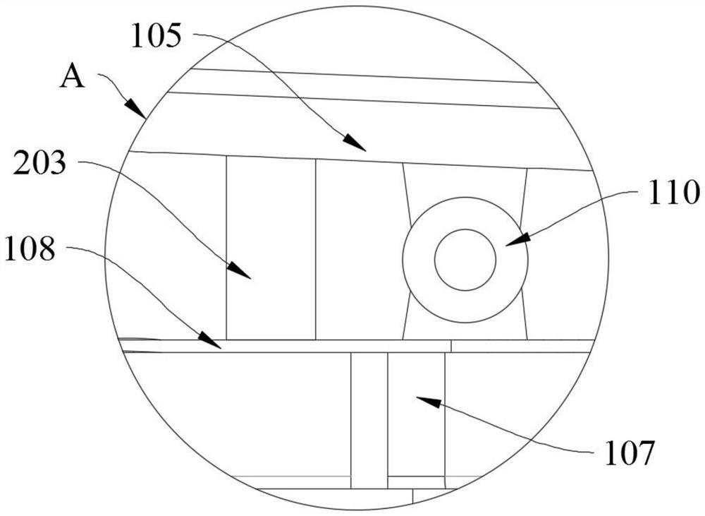
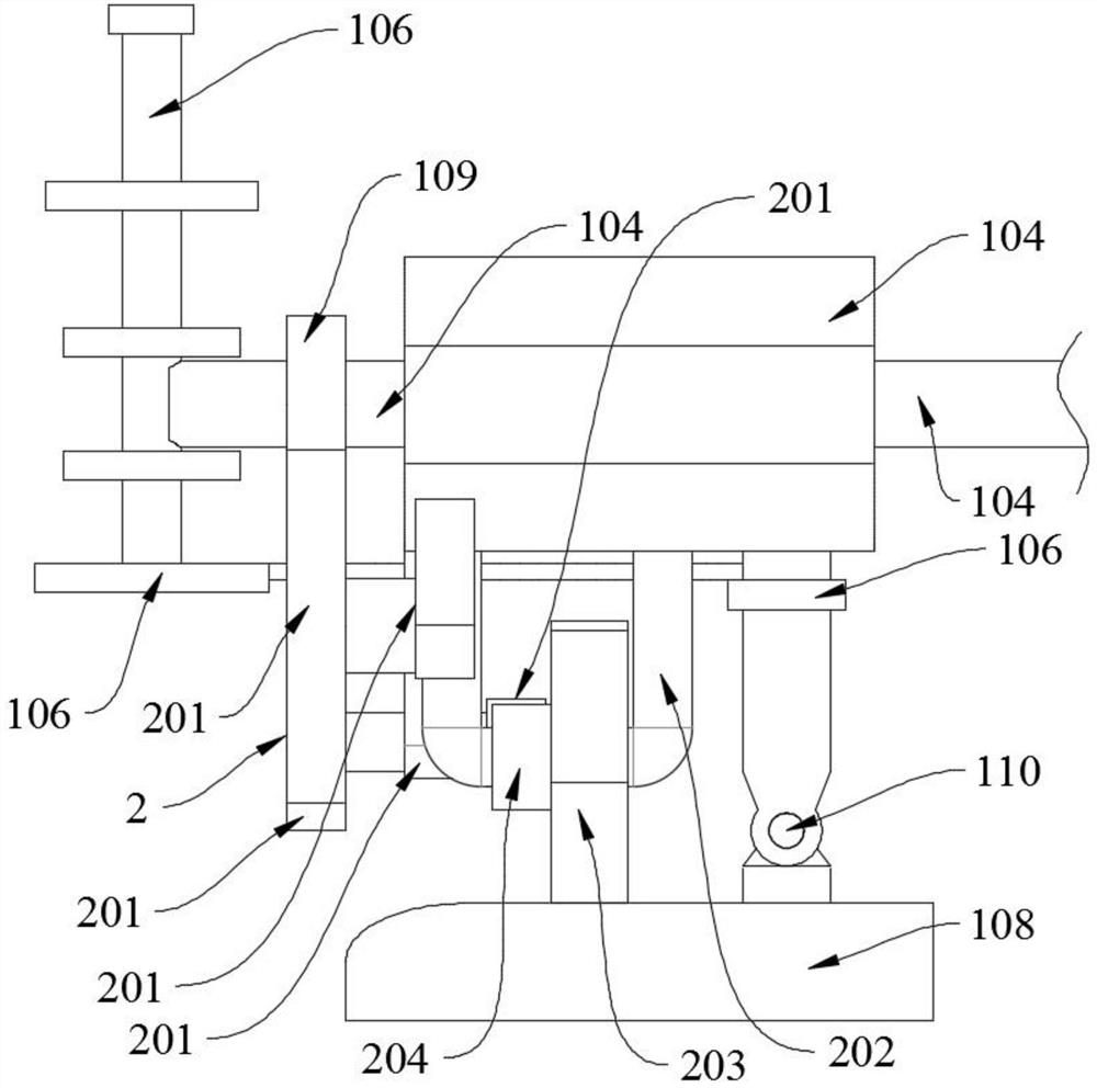

Image

  • Electric fan based on control of oscillating air supply mechanism and swing assembly
  • Electric fan based on control of oscillating air supply mechanism and swing assembly
  • Electric fan based on control of oscillating air supply mechanism and swing assembly

Examples


Embodiment Construction

[0033] The following will clearly and completely describe the technical solutions in the embodiments of the present invention with reference to the accompanying drawings in the embodiments of the present invention. Obviously, the described embodiments are only some, not all, embodiments of the present invention. Based on the embodiments of the present invention, all other embodiments obtained by persons of ordinary skill in the art without creative efforts fall within the protection scope of the present invention.

[0034] In describing the present invention, it is to be understood that the terms "opening", "upper", "lower", "thickness", "top", "middle", "length", "inner", "surrounding" etc. Indicating orientation or positional relationship is only for the convenience of describing the present invention and simplifying the description, and does not indicate or imply that the components or elements referred to must have a specific orientation, be constructed and operated in a sp...


PUM


Abstract

The invention discloses an electric fan based on control of an oscillating air supply mechanism and a swing assembly, and relates to the technical field of household appliances. The electric fan comprises an electric fan body and the swing assembly; the swing assembly is mounted on a fan head; the swing assembly comprises a gear set, a fixed supporting rod and a rotating head; the two end surfacesof the fixed supporting rod are fixedly installed on the fan head; a rotating head is rotationally matched with the peripheral surfaces of the fixed supporting rod; a gear A is arranged on one side surface of the rotating head; the gear set is in meshing transmission with the gear A; a supporting plate is fixed to the tops of supports; the upper surface of the supporting plate is contacted with the peripheral surface of the rotating head; a gear B is fixed on the circumferential surface of a motor; and the motor and the rotating head are in meshing transmission through the gear B, the gear set and the gear A. Through the effect of the swing assembly, the height of the support is adjusted to be flush with lower limbs, then the electric fan is turned on, the fan head completes repeated actions of raising from the horizontal direction and then switching to the head-up direction, and air blowing can be conducted on the head, the body, the lower limbs and other parts.

Description

technical field [0001] The invention belongs to the technical field of household appliances, and in particular relates to an electric fan controlled based on an oscillating air supply mechanism and an oscillating assembly. Background technique [0002] At present, the swing direction of the electric fan is relatively single, which cannot meet the diverse needs of people now. For example, the fan heads of the current general electric fans are all swinging on the horizontal plane; The fan is blown at the row position; the traditional electric fan that swings on the horizontal plane cannot meet the requirements. [0003] Wherein, for example, when a person stands in front of an electric fan and needs to blow the head, body, and lower limbs; obviously the electric fan that swings on the traditional horizontal plane cannot meet the requirements. [0004] An electric fan controlled by the oscillating air supply mechanism and the oscillating assembly of the present invention can ...

Claims


Application Information

Patent Timeline
IPC IPC(8): F04D25/10F04D29/00F04D27/00
CPCF04D25/105F04D27/007F04D29/002
Inventor 雷振兴
Owner 合肥智瑞工程科技有限公司
Features
  • R&D
  • Intellectual Property
  • Life Sciences
  • Materials
  • Tech Scout
  • Unparalleled Data Quality
  • Higher Quality Content
  • 60% Fewer Hallucinations
Learn More