
A Spherical Parallel Mechanism with Large Rotation Range

A parallel and range technology, which is applied in the direction of manipulators, program-controlled manipulators, manufacturing tools, etc., can solve the problems of insufficient rigidity and small working range of spherical parallel mechanisms, and achieve the goal of increasing the rotation range, increasing stiffness and reducing force Effect

Active Publication Date: 2021-04-16
NANJING UNIV OF SCI & TECH
View PDF7 Cites 0 Cited by
  • Summary
  • Abstract
  • Description
  • Claims
  • Application Information

AI Technical Summary

Problems solved by technology

[0004] The technical problem solved by the present invention is to provide a spherical parallel mechanism with a large rotation range to solve the problems of small working range and insufficient rigidity of the spherical parallel mechanism.

Method used


Image

  • A Spherical Parallel Mechanism with Large Rotation Range
  • A Spherical Parallel Mechanism with Large Rotation Range
  • A Spherical Parallel Mechanism with Large Rotation Range

Examples


Embodiment Construction

[0025] In order to illustrate the technical scheme and technical purpose of the present invention, the present invention will be further introduced below in conjunction with the accompanying drawings and specific embodiments.

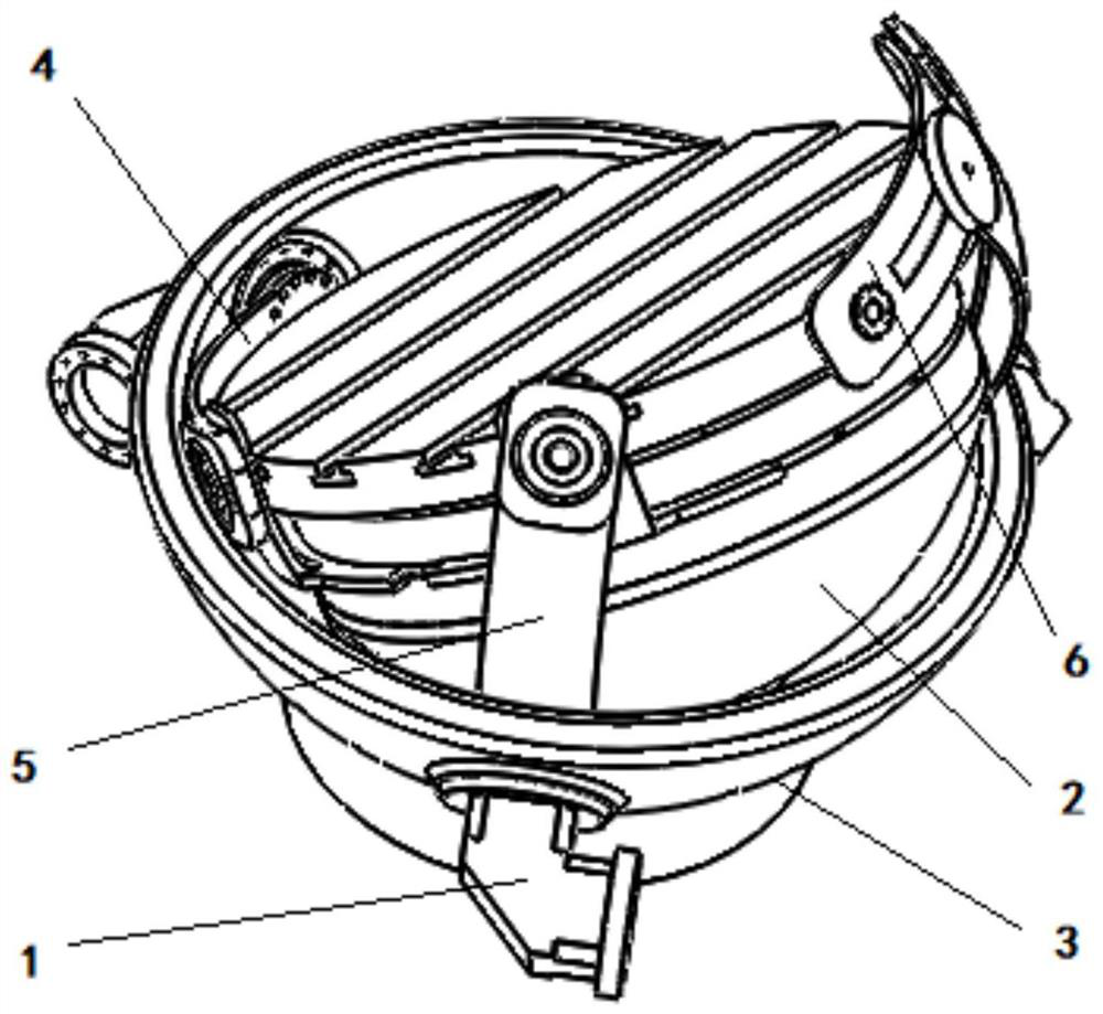
[0026] combine figure 1 , a spherical parallel mechanism with a large rotation range of the present invention includes a static platform 3, three speed reducers 1 evenly distributed on the static platform 3, a moving platform 2 arranged in the circular cavity of the static platform 3, a first Branch chain 4, second branch chain 5, third branch chain 6;

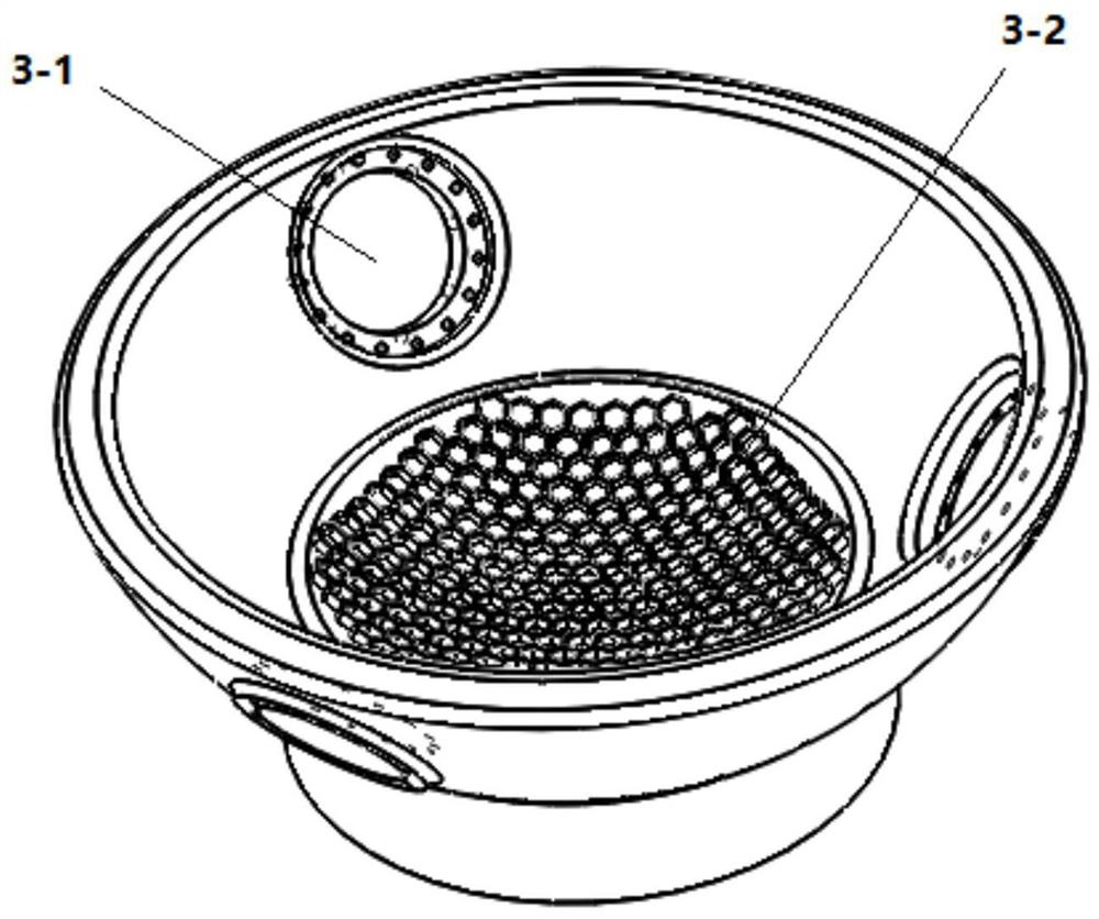
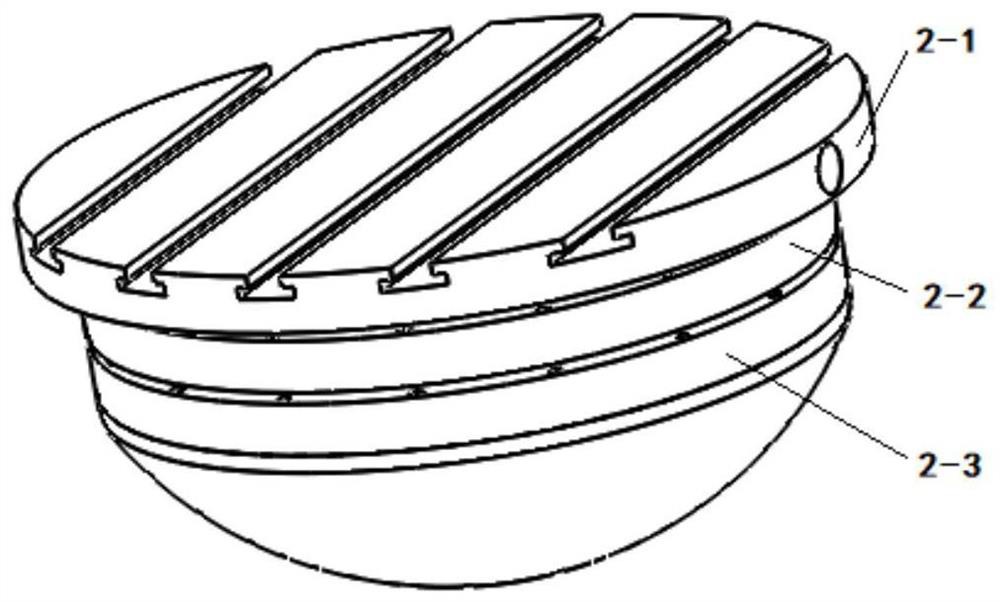
[0027] combine Figure 2-Figure 10 , the static platform 3 is provided with the installation hole 3-1 of the reducer 1, and the axial direction of the three installation holes 3-1 intersects with the spherical center of the static platform 3, and the axial directions of the three installation holes 3-1 are two The two included angles are 120°; the moving platform 2 includes a working table 2-1, a rota...


PUM


Abstract

The invention discloses a spherical parallel mechanism with a large rotation range, which comprises a static platform, three reducers symmetrically arranged on the static platform, a dynamic platform arranged in the circular cavity of the static platform, a first branch chain, a second branch chain and the third branch chain; one end of the first branch chain and the second branch chain are respectively coaxially connected with the rotating ring of the moving platform and the base of the moving platform, and the other end is coaxially connected with the reducer at the installation hole of the static platform for Control the pitch and tilt of the braking platform; one end of the third branch chain is connected to the worktable of the moving platform through a shaft, and the other end is coaxially connected with the reducer at the installation hole of the static platform to control the rotation of the braking platform; the unloading device is located at Between the moving platform and the static platform, and in contact with both at the same time. The reducer is used to control the rotation of each branch chain, and all the rotating pairs on the three branch chains are intersected at the center of the ball, which makes the mechanism decoupled. The spherical surface parallel mechanism of the invention has high rigidity, large rotation range and high decoupling precision.

Description

technical field [0001] The invention belongs to the field of parallel mechanisms, in particular to a spherical parallel mechanism with a large rotation range. Background technique [0002] All the rotating pairs of the usual spherical mechanism rotate around the center of the sphere. Take the three-degree-of-freedom spherical mechanism as an example. When the center of mass of the moving platform is at the center of the sphere, it has the smallest moment of inertia, which is convenient for quick angle adjustment. This kind of mechanism has been partially effectively used under some light load conditions, such as electronic eyes, camera heads, etc. However, for the CNC rotary table, its application is limited due to problems such as rigidity, bearing capacity, and range of motion. For this kind of workbench, it needs not only a large range of motion and simple decoupling, but also a small moment of inertia to improve the fast tracking ability, and it also needs to bear heav...

Claims


Application Information

Patent Timeline
Patent Type & Authority Patents(China)
IPC IPC(8): B25J9/00
CPCB25J9/003
Inventor 李开明熊万涛张阳郑伟张亚军舒阳董立磊葛帅帅
Owner NANJING UNIV OF SCI & TECH
Learn More