Cam type conversion guide rail sliding block

A technology of changing guide rail and cam type, which is applied in the field of rail transmission, can solve the problems of small load, inability to intersect the arrangement of guide rails, and inability to freely switch sliders, etc., and achieve the effects of strong load capacity, smooth rolling, and scientific and reasonable configuration

Inactive Publication Date: 2020-11-06
郭嘉辉
View PDF7 Cites 0 Cited by
  • Summary
  • Abstract
  • Description
  • Claims
  • Application Information

AI Technical Summary

Problems solved by technology

[0003] The guide rail slider in the prior art is generally in the form of a single guide rail, and the guide rails cannot be arranged intersecting
If it is necessary to intersect multiple guide rails to form a mobile network hub, the slider cannot freely switch between multiple guide rails and cannot meet the requirements of complex motion trajectories.
Even if multiple guide rails intersect, the cooperation between the guide rail and the slider should not be too complicated, the load that can be borne is small, and it is difficult to ensure smooth switching of routes at the intersection of guide rails

Method used


Image

  • Cam type conversion guide rail sliding block
  • Cam type conversion guide rail sliding block
  • Cam type conversion guide rail sliding block

Examples


Embodiment

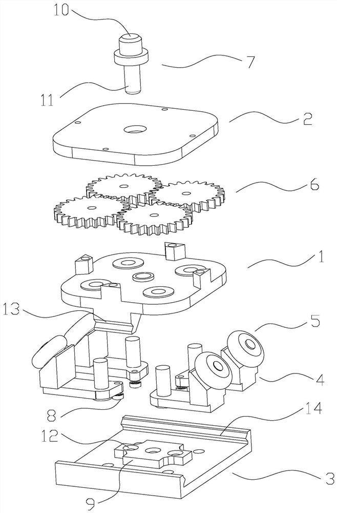
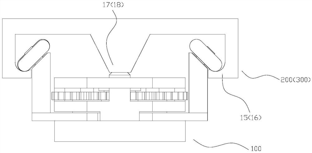
[0041] see Figure 1 to Figure 4 , the present invention provides a cam-type conversion guide rail slider, a slider 100 and cross-arranged longitudinal rails 200 and cross rails 300;

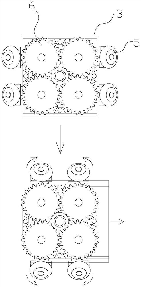
[0042] Wherein, the sliding block 100 includes a base 1, a cover 2, a flange sliding table 3, a swing claw 4, a guide wheel 5, a torsion spring (not shown), a return spring (not shown), a gear 6 and a locking pin 7 The four swing claws 4 are rotationally connected with the four corners of the abutment 1 through pin shafts, so that the four swing claws 4 can swing at 90° at the four corners of the abutment 1, and each swing claw 4 is provided with a swing terminal 8 at the bottom of the swing. The terminal 8 and the swing claw 4 swing synchronously around the pin shaft, and a torsion spring is provided between the swing claw 4 and the base 1; a pin hole is provided in the center of the base 1; On the base 1 and correspondingly connected to the pin shaft transmission of each swing claw 4, it rota...


PUM


Abstract

The invention provides a cam type conversion guide rail sliding block. The cam type conversion guide rail sliding block is characterized by comprising a sliding block body, a longitudinal rail and a transverse rail, wherein the longitudinal rail and transverse rail are arranged crosswise, the sliding block body comprises a base platform, a sealing cover, a flange sliding table, swing claws, guidewheels, a torsion spring, a reset spring, gears and a locking pin; the four swing claws are rotationally connected with the four corners of the base platform through pins, and a swing terminal is arranged at the bottom of each swing claw; the guide wheels are rotationally mounted outside the swing claws; each gear is positioned on the base platform and is correspondingly in transmission connectionwith the pin of each swing claw; the flange sliding table is slidably connected below the base platform in the transverse direction, and the top of the flange sliding table is provided with push blocks matched with each swing terminals; a longitudinal outer rail and a transverse outer rail are mutually crossed at the junction of the longitudinal rail and the transverse rail, and arc-shaped railsmatched with the swing arcs of the swing claws are arranged at the junction of the longitudinal rail and the transverse rail, so that the guide wheels can roll between the longitudinal outer rail andthe transverse outer rail in a reversing mode through the arc-shaped rails. According to the cam type conversion guide rail sliding block, the multiple guide rails are arranged in an intersecting mode, and the sliding blocks can be freely switched on the tracks of the multiple guide rails.

Description

technical field [0001] The invention relates to the field of track transmission, in particular to a cam type conversion guide rail slider. Background technique [0002] The guide rail slider is a commonly used transmission part in the mechanical field. The parts that need to be transmitted can be fixedly connected to the slider, so that they can slide freely along the track of the guide rail. [0003] The guide rail slider in the prior art is generally in the form of a single guide rail, and the guide rails cannot be intersected. If it is necessary to intersect multiple guide rails to form a mobile network hub, the slider cannot freely switch between multiple guide rails, and cannot meet the requirements of complex motion trajectories. Even if multiple guide rails intersect, the cooperation between the guide rail and the slider should not be too complicated, the load that can be borne is small, and it is difficult to ensure smooth switching of routes at the intersection of ...

Claims


Application Information

Patent Timeline
Patent Type & Authority Applications(China)
IPC IPC(8): F16C29/04
CPCF16C29/008F16C29/04
Inventor 郭嘉辉
Owner 郭嘉辉
Why Eureka
Try Eureka