
Drain pipe clogging monitoring device and drain pipe clogging monitoring system

A monitoring device and monitoring system technology, applied in waterway systems, water supply devices, measuring devices, etc., can solve problems such as reverse flow, inability to simply confirm the blockage of drain pipes, and useless cleaning operations.

Active Publication Date: 2020-11-10
MITSUBISHI ELECTRIC BUILDING SOLUTIONS CORP
View PDF18 Cites 0 Cited by
  • Summary
  • Abstract
  • Description
  • Claims
  • Application Information

AI Technical Summary

Problems solved by technology

[0012] However, since the drain pipe is buried in the ground of the building, etc., it is not possible to easily confirm the clogging in the drain pipe
In addition, regular cleaning can also be considered, but since the clogging situation varies depending on the store, if it is not so clogged, it will become a useless cleaning operation.
In addition, there may be waste in cost
Conversely, if the interval between cleaning operations is excessively separated, as described above, backflow of drainage may also occur.

Method used


Image

  • Drain pipe clogging monitoring device and drain pipe clogging monitoring system
  • Drain pipe clogging monitoring device and drain pipe clogging monitoring system
  • Drain pipe clogging monitoring device and drain pipe clogging monitoring system

Examples


Embodiment Construction

[0028] Hereinafter, preferred embodiments of the present invention will be described with reference to the drawings.

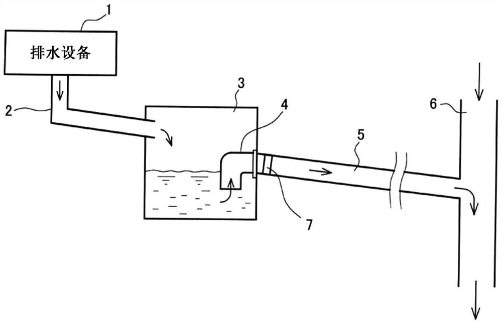
[0029] figure 1 It is a conceptual diagram showing a main part of a drainage piping facility installed in a building such as a shopping center for discharging drainage from a drainage facility 1 of a restaurant in the shopping center to the outside. figure 1 Shown is a drainage piping facility including a miscellaneous drainage pipe 2 , a drainage bucket (catchment bucket) 3 , an elbow 4 for a drainage elbow, a drainage horizontal branch pipe 5 , and a vertical pipe 6 . It is assumed that the drainage discharged from the drainage device 1 is a sink at the kitchen or drainage discharged from a drain outlet on the ground. Drainage may contain fats, food residues, powders, etc. (hereinafter collectively referred to as "fats") that cause clogging of drain pipes.

[0030] Such as figure 1 As shown by the middle arrow, the drainage discharged from the drainage eq...


PUM


Abstract

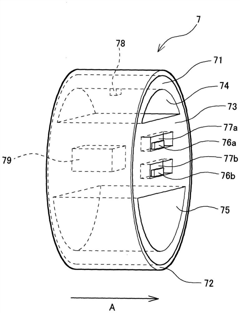
Provided are a drain pipe clogging monitoring device and a drain pipe clogging monitoring system. The present invention makes it possible to easily monitor the clogging situation of a horizontal pipewithout visual observation. The drain pipe clogging monitoring device (7) is provided with a tubular main body frame (71) attached to the vicinity of the drain inflow side of a drain lateral branch pipe; a rubber pad (72) attached to the entire outer periphery of the main body frame (71); a main body part (73) arranged in the central part; a drainage through-hole (75) that is provided below the main body section (73) and that maintains the amount of drainage flowing into the drainage lateral branch pipe constant; and an air through-hole (74) provided above the main body section (73). Water detection sensors (76a, 76b) are arranged in the vertical direction on the side surface of the main body (73) on the drain water outflow side, thereby detecting the water level of the drain water flowingback from the drain water outflow side.

Description

technical field [0001] The present invention relates to a drainage pipe clogging monitoring device and a drainage pipe clogging monitoring system, in particular to the monitoring of horizontal pipe clogging. Background technique [0002] For example, the drainage from a restaurant in a building such as a shopping mall is sent to the standpipe (main pipe) of the shopping center through the drainage pipe in the store through the drainage bucket and the lateral drainage pipe, and then discharged to the outside. [0003] However, in restaurants that use a lot of fats and oils, the possibility of clogged drains is relatively higher. And, when the clogging situation is severe, the drainage that flows into the drainage horizontal branch pipe from the drainage bucket sometimes flows backwards without being discharged from the standpipe, and the store is flooded. In order to eliminate such a situation, it is necessary to clean the drain pipe before the degree of clogging becomes ser...

Claims


Application Information

Patent Timeline
Patent Type & Authority Applications(China)
IPC IPC(8): E03F7/00G01D21/02
CPCE03F7/00G01D21/02
Inventor 谷口明
Owner MITSUBISHI ELECTRIC BUILDING SOLUTIONS CORP
Learn More