
Table frame convenient to assemble

A technology that facilitates assembly and table stand. It is applied to the legs of general furniture, tables that can change the height of the table, tables, etc. It can solve the problems of troublesome installation, unfriendly users, and the lifting platform is not assembled properly, and achieves low precision requirements. Manufacturing cost controllable effect

Pending Publication Date: 2020-11-13
ZHEJIANG JIECHANG LINEAR MOTION TECH
View PDF0 Cites 1 Cited by
  • Summary
  • Abstract
  • Description
  • Claims
  • Application Information

AI Technical Summary

Problems solved by technology

[0002] Electric lift tables are becoming more and more popular in the field of office and home. Because electric lift tables take up a lot of space and are inconvenient to transport, the current manufacturers of lift platforms are usually not assembled when they leave the factory. Self-assembled or assembled by the manufacturer, so how to realize fast assembly or convenient assembly is an urgent problem to be solved for the current lifting platform or electric lifting platform
[0003] The main components of the current electric lifting table are the table frame and the desktop, and the table frame usually includes a beam and a lifting column. Usually, the later assembly is mainly between the beam and the lifting column. At present, the lifting column and the beam are basically two independent parts. When assembling, the user needs to fix the lifting column and the beam with the help of fasteners such as screws. This connection and fixing method is unfriendly to the user and needs to be installed with the help of tools. Moreover, the current table frame, in the The end of the beam is usually installed with side panels to strengthen the support strength, and the side panels also need to be installed separately, so the overall installation is more troublesome

Method used


Image

  • Table frame convenient to assemble
  • Table frame convenient to assemble
  • Table frame convenient to assemble

Examples


Embodiment 1

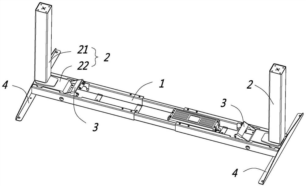
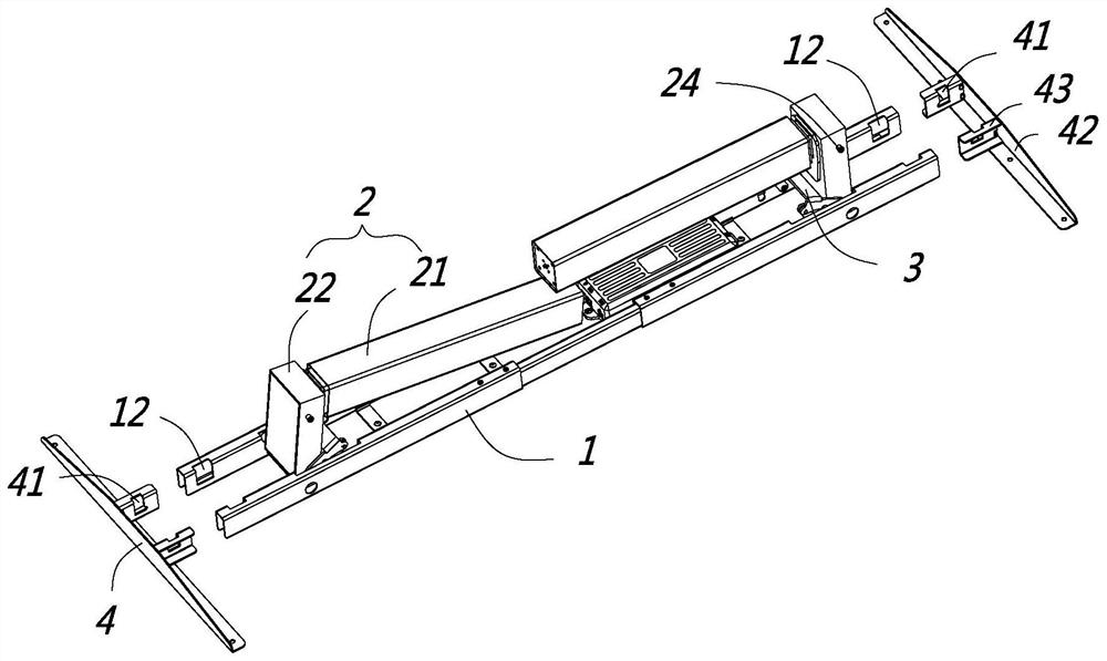
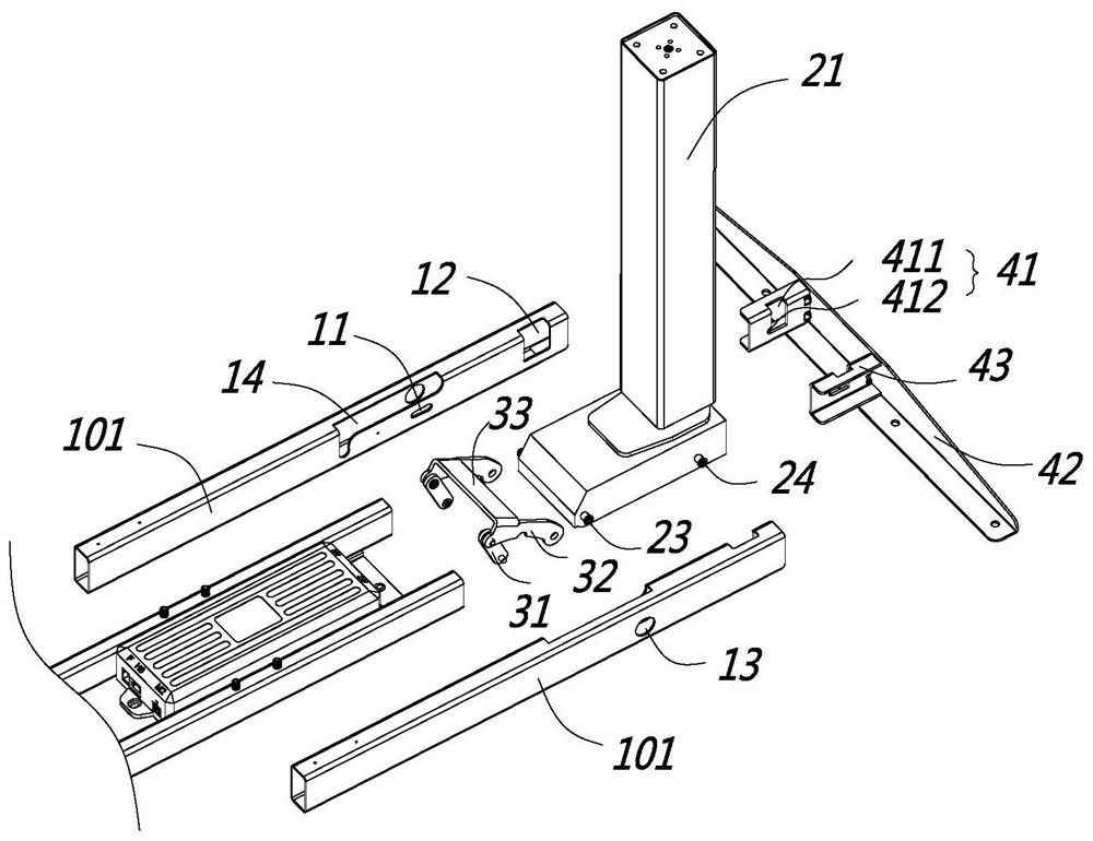
[0030] Such as Figure 1 to Figure 5 As shown, the present embodiment is a table frame for easy assembly, including a crossbeam 1. For the convenience of the following description, the length direction of the crossbeam 1 is defined as the transverse direction, and the width direction of the crossbeam 1 is defined as the longitudinal direction. There is a lifting column 2, the table frame also includes a side plate 4 detachably connected to the end of the beam 1, the lifting column 2 includes a top shell 22 and a column part 21, the lifting column 2 in this embodiment is preferably It is an electric lifting column, and a transmission assembly is arranged in the column part 21. The transmission assembly is driven by a driving motor, and the driving motor is arranged in the top housing 22. Since the internal structure of the electric lifting column is widely disclosed in the prior art, this article I won't go into too much detail. In this embodiment, the top case 22 includes a p...


PUM


Abstract

The invention discloses a table frame convenient to assemble. The invention belongs to the field of electric lifting tables. The table frame comprises a cross beam, a lifting stand column is installedon the cross beam, the table frame further comprises side plates detachably connected to the ends of the cross beams, the lifting stand column comprises a top shell, the top shell comprises a positioning end and a stress end, the positioning end comprises a locking pin, locking holes are formed in the side plates, an avoiding hole for avoiding the locking hole is formed in the cross beam, duringassembly, the locking pin penetrates through the receding hole to enter the locking hole, a locking element is installed on the cross beam, the locking element pulls or extrudes the stress end of thetop shell so that the locking pin can be locked in the locking hole, and meanwhile the locking pin extrudes the locking hole so that the side plate and the end of the cross beam can be extruded and fixed. The table frame has the advantage that a purchaser can assemble the table frame more quickly and conveniently.

Description

【Technical field】 [0001] The invention relates to a conveniently assembled table frame, which belongs to the field of electric lifting tables. 【Background technique】 [0002] Electric lift tables are becoming more and more popular in the field of office and home. Because electric lift tables take up a lot of space and are inconvenient to transport, the current manufacturers of lift platforms are usually not assembled when they leave the factory. Self-assembled or assembled by the manufacturer, so how to realize fast assembly or convenient assembly is an urgent problem to be solved for the current lifting platform or electric lifting platform. [0003] The main components of the current electric lifting table are the table frame and the desktop, and the table frame usually includes a beam and a lifting column. Usually, the later assembly is mainly between the beam and the lifting column. At present, the lifting column and the beam are basically two independent parts. When as...

Claims


Application Information

Patent Timeline
IPC IPC(8): A47B13/02A47B9/00A47B3/06
CPCA47B3/06A47B9/00A47B13/02
Inventor 陆小健张东行马勇
Owner ZHEJIANG JIECHANG LINEAR MOTION TECH
Learn More