Supercharge Your Innovation With Domain-Expert AI Agents!

Automatic balancing type soft top drainage method and device

An automatic balancing and drainage device technology, applied in the direction of roof drainage, roofing, roof covering, etc., can solve the problem of water accumulation that cannot be eliminated, and achieve the effect of simple structure, constant water inlet and outlet level, and convenient use

Pending Publication Date: 2020-11-13
SHENYANG AEROSPACE XINLE
View PDF0 Cites 0 Cited by
  • Summary
  • Abstract
  • Description
  • Claims
  • Application Information

AI Technical Summary

Problems solved by technology

After continuous rain, with the increase of accumulated water, the mass distribution of accumulated water and soft roof will change without support under the soft roof. Continuously moving towards the sorghum (eg Figure 4 shown), due to the accumulation of water that cannot be removed, when it exceeds the soft top's bearing limit, it will cause damage to the soft top

Method used


Image

  • Automatic balancing type soft top drainage method and device
  • Automatic balancing type soft top drainage method and device
  • Automatic balancing type soft top drainage method and device

Examples


Embodiment 1

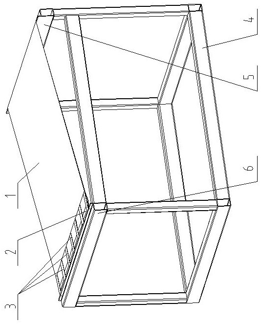
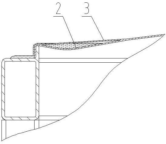
[0017] Such as figure 1 As shown, the self-balancing soft top drainage device includes a soft top 1 and a base 4. There are high beams 5 and low beams 6 on the base 4, and the two ends of the soft top 1 are respectively fixed on the high beams 5 and low beams 6. The end of the soft top 1 close to the low beam 6 is divided into a hollow upper layer 3 and a lower layer 2 provided with grooves, and the soft top 1 is tightened under the joint action of the upper layer 3 and the upper end of the soft top 1 . Since the upper layer is a hollow structure, water can flow freely to the lower layer 2; the groove is made of the same material as the upper layer, only because the lower layer 2 is looser than the upper layer 3, and the lower ends of the upper layer 3 and the lower layer 2 are jointly arranged on the top surface of the low beam 6 superior.

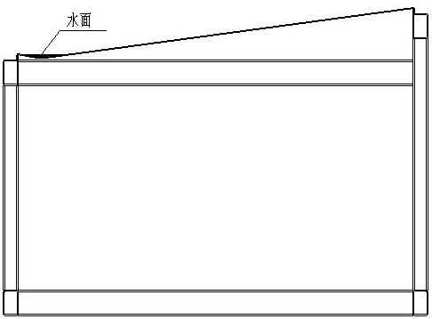
[0018] Such as figure 2 As shown, when the soft top is in the rain state, the rainwater flows from the high beam end of the soft top...

Embodiment 2

[0020] Such as image 3 As shown, the self-balancing soft top drainage device includes a soft top 1 and a base 4, a high beam 5 and a low beam 6 are arranged on the base 4, and a high connection point 7 and a low connection point 8 are arranged on the low beam 6, and the high connection point 7 and the low connection point 8 are arranged on two horizontal planes respectively. One end of the soft top 1 is fixed on the high beam 5, and the other end close to the low beam 6 is divided into a hollow upper layer 3 and a lower layer 2 with grooves, the hollow upper layer 3 is connected to the high connection point 7, and the soft top 1 is tightened ; The lower floor 2 is connected to the low connection point 8 of the low beam 6, and because the lower floor 2 is looser than the upper floor 3, a groove is formed. When the soft top 1 is in the rain state, the rainwater flows from the 5 end of the high beam to the 6 end of the low beam of the soft top 1, and collects in the groove, and ...


PUM


Abstract

The invention relates to an automatic balancing type soft top drainage method and device. By means of the automatic balancing type soft top drainage method and device, large-area, small-inclination and supporting-free drainage of a soft top can be effectively achieved through a simple structure. According to the automatic balancing type soft top drainage method, water falling on the soft top flowstowards the lower beam end from the high beam end, passes through a hollowed-out upper layer and is collected into a groove in the lower layer, the water surface rises, the position of the gravity center of accumulated water in the groove slightly moves towards the high beam end under the mutual action of the weight of the water, the tension of the upper end and the upper layer of the lower end of the soft top and the deformation force of the soft top, water is drained from the upper surface of a low beam when the liquid level exceeds the lower beam, and automatic balancing of the water inletvolume and the drainage volume of the groove is achieved.

Description

technical field [0001] The invention relates to an automatic balancing soft roof drainage method and a device thereof. Background technique [0002] The soft roof structure is often used in engineering. The traditional unsupported soft roof needs a large inclination angle to achieve smooth drainage. Otherwise, it is necessary to set up hard supports under the soft roof to ensure the drainage of the soft roof. Otherwise, water accumulation and damage will occur The problem with the soft top. The reason is: the soft top is in the rain state, and the rainwater flows from the high beam end of the soft top to the low beam end, causing the soft top near the low beam end to form a water storage groove (such as image 3 shown). After continuous rain, with the increase of accumulated water, the mass distribution of accumulated water and soft roof will change without support under the soft roof. Continuously moving towards the sorghum (eg Figure 4 As shown), due to the accumulatio...

Claims


Application Information

Patent Timeline
Patent Type & Authority Applications(China)
IPC IPC(8): E04D13/04
CPCE04D13/0404E04D13/0481
Inventor 林绍勇杜啸付建孙传洋王琳
Owner SHENYANG AEROSPACE XINLE
Features
  • R&D
  • Intellectual Property
  • Life Sciences
  • Materials
  • Tech Scout
  • Unparalleled Data Quality
  • Higher Quality Content
  • 60% Fewer Hallucinations
Learn More