

Threaded positioning pin structure for unmanned aerial vehicle assembly
A technology of positioning pins and drones, which is applied to bolts, workpiece clamping devices, manufacturing tools, etc., can solve problems such as low production efficiency, short production operation time, and complicated clamping methods, so as to achieve convenient operation and improve production efficiency , the effect of reducing the number of parts
- Summary
- Abstract
- Description
- Claims
- Application Information
AI Technical Summary
Problems solved by technology
Method used
Image

Examples
Embodiment Construction
[0020] This embodiment is a threaded positioning pin structure used for assembling an unmanned aerial vehicle.
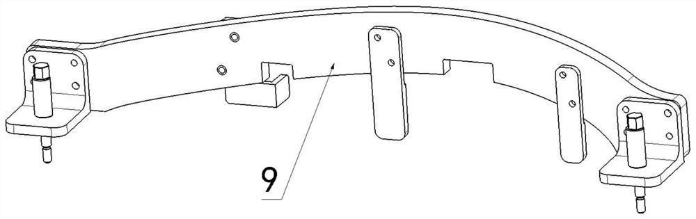
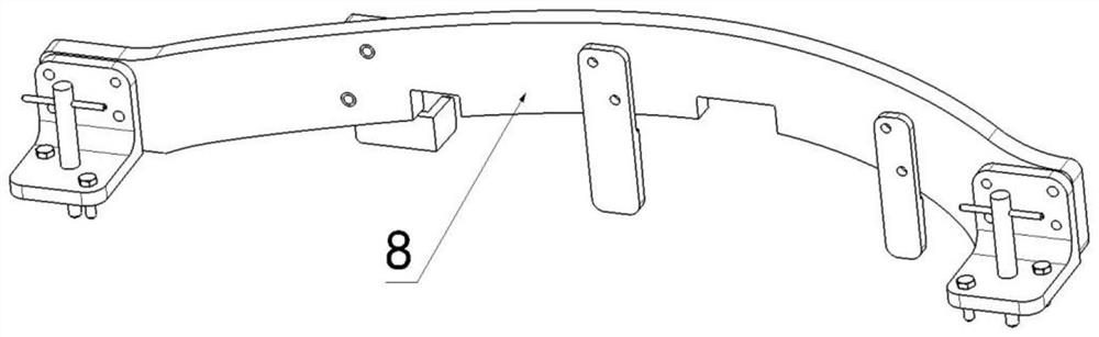
[0021] refer to figure 1 , figure 2 , the present embodiment is used in the assembly of the UAV. The structure of the threaded positioning pin is composed of a positioning pin body, a corner seat and a clamping plate assembly. The positioning pin body is matched with the corner seat. At the inner edge of the plane at the end of the plate, the corner seat and the clamping plate are fixedly connected by bolts.
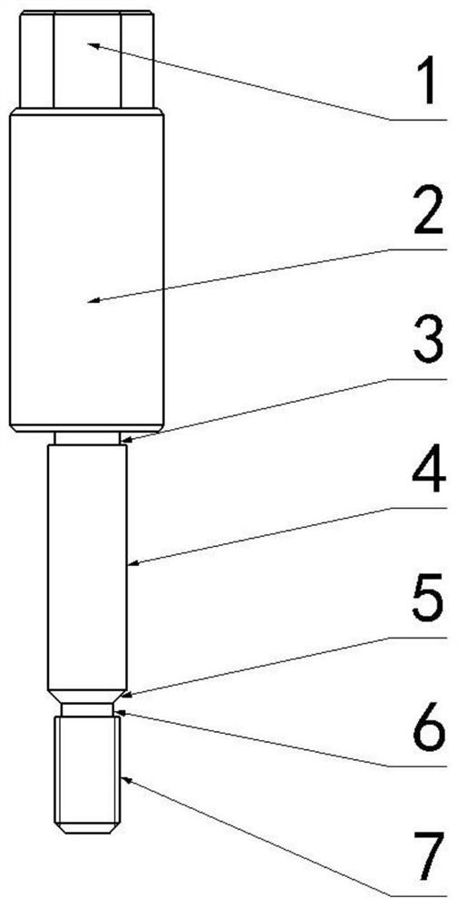
[0022] The structure of the positioning pin body is from the upper end down to the outer hexagonal section 1, the pin handle 2, the first relief groove 3, the positioning pin rod 4, the guide section 5, the second relief groove 6, and the thread section 7; The hexagonal section 1 is used to cooperate with the hexagonal pneumatic sleeve of the pneumatic tool. According to the thread size of the threaded section 7, refer to the corresponding bolt head specif...
PUM
| Property | Measurement | Unit |
|---|---|---|
| Length | aaaaa | aaaaa |
Abstract
Description
Claims
Application Information