Injection mold device

An injection mold and mold technology, applied in the field of injection mold devices, can solve problems such as depression, leakage of injected raw materials, damage to equipment, etc., and achieve the effect of increasing the hardening time of raw materials, prolonging the service life, and avoiding sticking.

Active Publication Date: 2020-11-17
福捷(武汉)电子配件有限公司
View PDF16 Cites 3 Cited by
  • Summary
  • Abstract
  • Description
  • Claims
  • Application Information

AI Technical Summary

Problems solved by technology

[0003] The existing patent No. CN107139398B proposes an injection mold, which has the advantage that the mold is less affected by temperature changes, but in the injection molding process, it is inevitable that due to maintenance errors or power source failures, two molds The junction is not tight enough or there is a depression. At this time, the injection of raw materials will cause leakage. The leaked raw materials will accumulate in the gap between the two molds, and after hardening, the two molds will stick together, resulting in damage to the tensile force generated when the power source pulls the mould. Equipment, and the process of separating and cleaning the two molds is extremely difficult, and the above molds have not been improved for the above conditions

Method used


Image

  • Injection mold device
  • Injection mold device
  • Injection mold device

Examples


Embodiment 1

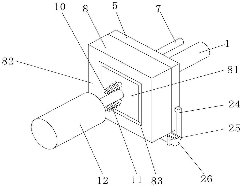
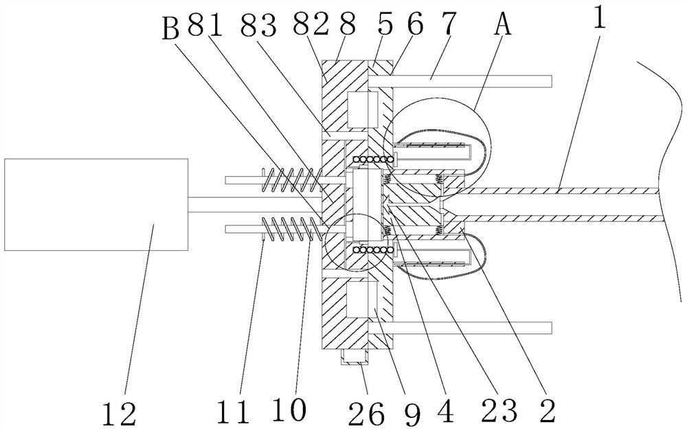
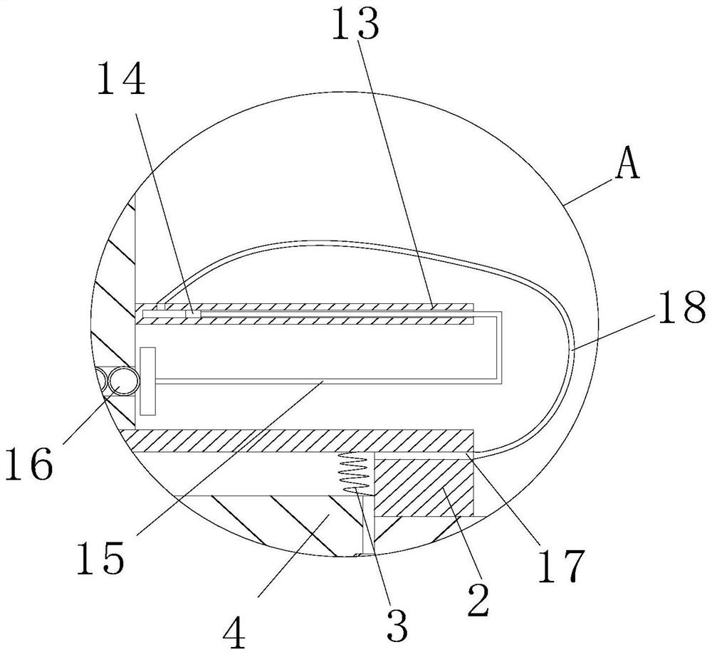
[0038] Example 1: Please refer to Figure 1-7 , an injection mold device, comprising an injection gun head 1, a fixed mold 5, a movable mold 8 and a hydraulic cylinder 12, the injection gun head 1 is a hollow cylinder, and the outer wall of the right end of the injection gun head 1 is fixedly connected with a guide tube 2, The plastic guide cylinder 2 is a hollow rectangular body, the right side of the plastic guide cylinder 2 is provided with a hole and the injection gun head 1 is located in the hole, the top surface and the bottom inner wall of the plastic guide cylinder 2 are fixedly connected with a group of springs A3, two One end of the group spring A3 far away from the inner wall of the plastic guide tube 2 is fixedly connected with a clamp block 4, the clamp block 4 is a quarter ellipsoid, and the front and rear wall surfaces and the left and right wall surfaces of the clamp block 4 are all bonded to the inner wall of the plastic guide tube 2, The gap between the two c...

Embodiment 2

[0045] Example 2: Please refer to Figure 8-9, on the basis of Embodiment 1, the transmission shaft of the hydraulic cylinder 12 is fixedly connected with the connecting plate 27, and the connecting plate 27 is fixedly equipped with a detection sensor 28, the detection sensor 28 corresponds to the position of the outer frame 82, and through the setting of the detection sensor 28, The detection sensor 28 is used to detect the position of the outer frame 82, so that when the outer frame 82 is out of contact with the fixed mold 5 during the injection molding process, a signal is sent in time to cooperate with the control circuit to perform functions such as alarming and retracting the transmission shaft of the hydraulic cylinder 12.

[0046] The right side of the piston rod 15 is fixedly connected with a detection cylinder 29, the detection cylinder 29 is a hollow convex body, a thermometer 30 is fixedly installed in the detection cylinder 29, the detection end of the thermometer ...


PUM


Abstract

The invention relates to the technical field of injection molding, and discloses an injection mold device. The injection mold device comprises an injection molding gun head, a fixed mold, a movable mold and a hydraulic cylinder; the outer wall of the right end of the injection molding gun head is fixedly connected with a plastic guide barrel, and the inner walls of the top face and the bottom faceof the plastic guide barrel are each fixedly connected with a spring A; clamping blocks are fixedly connected with the ends, away from the inner wall of the plastic guide barrel, of the two springs A; the face, away from the injection molding gun head, of the plastic guide barrel is fixedly connected with the fixed mold; insertion holes A are formed in the upper end and the lower end of the sideface of the fixed mold correspondingly; each inserting hole is provided with an inserting rod in a sleeved mode, and the left ends of the two inserting rods are fixedly connected with the movable mold; and mold cavities are formed in the faces, corresponding to the movable mold, of the inserting rods. A circulating cooling pipe is separated from the fixed mold and the movable mold through injection molding pressure, the problem that resistance is increased and even blockage is caused due to raw material cooling in the injection molding process is avoided, and the circulating cooling pipe is automatically connected with the fixed mold and the movable mold after injection molding is completed, so that cooling molding of the raw materials is ensured.

Description

technical field [0001] The invention relates to the technical field of injection molding, in particular to an injection molding mold device. Background technique [0002] Injection molding is a method of producing and modeling industrial products. After combining two molds with power sources such as hydraulic cylinders, the melted plastic raw materials are injected into the cavity for cooling and molding to make plastic products of various shapes. [0003] The existing patent No. CN107139398B proposes an injection mold, which has the advantage that the mold is less affected by temperature changes, but in the injection molding process, it is inevitable that due to maintenance errors or power source failures, two molds The junction is not tight enough or there is a depression. At this time, the injection of raw materials will cause leakage. The leaked raw materials will accumulate in the gap between the two molds, and after hardening, the two molds will stick together, resulti...

Claims


Application Information

Patent Timeline
Patent Type & Authority Applications(China)
IPC IPC(8): B29C45/26B29C45/76B29C45/78
CPCB29C45/26B29C45/2602B29C45/76B29C45/78B29C2945/7604
Inventor 不公告发明人
Owner 福捷(武汉)电子配件有限公司
Why Eureka
Try Eureka