Automatic beauty sewing machine walking trolley
A technology of walking trolley and beautifying sewing machine, which is applied in the direction of construction and building construction, and can solve the problems of destroying beautifying seams, beautifying seam agents polluting the construction environment, and electric beautifying sewing machines not being able to walk smoothly.
- Summary
- Abstract
- Description
- Claims
- Application Information
AI Technical Summary
Problems solved by technology
Method used
Image
Examples
Embodiment 1
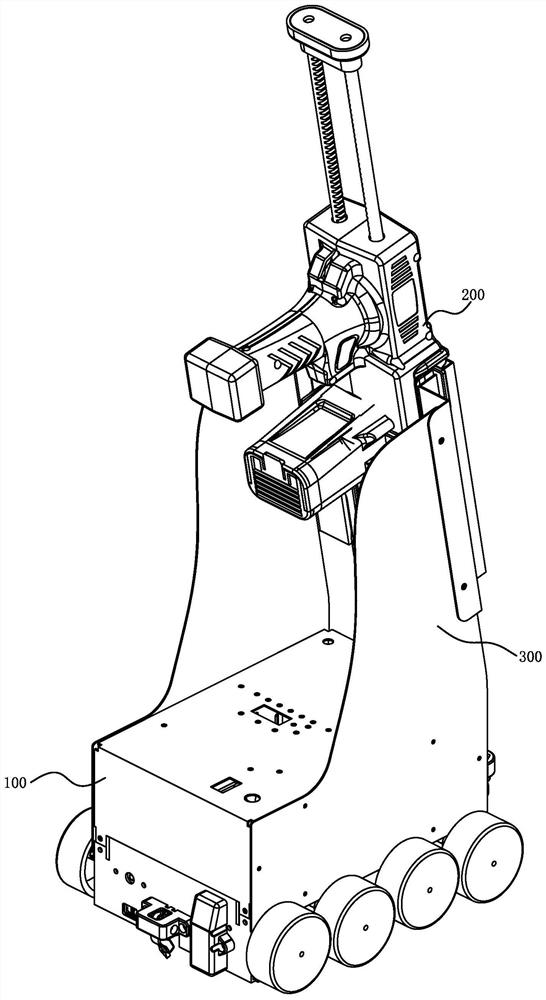
[0026] Embodiment one: if figure 1 As shown, the automatic beauty sewing machine includes a walking trolley 100, a beauty sewing gun 200 and a gun frame 300, the gun frame 300 is fixed on the walking trolley 100, and the beauty sewing gun 200 and the gun frame 300 are connected by plugging.
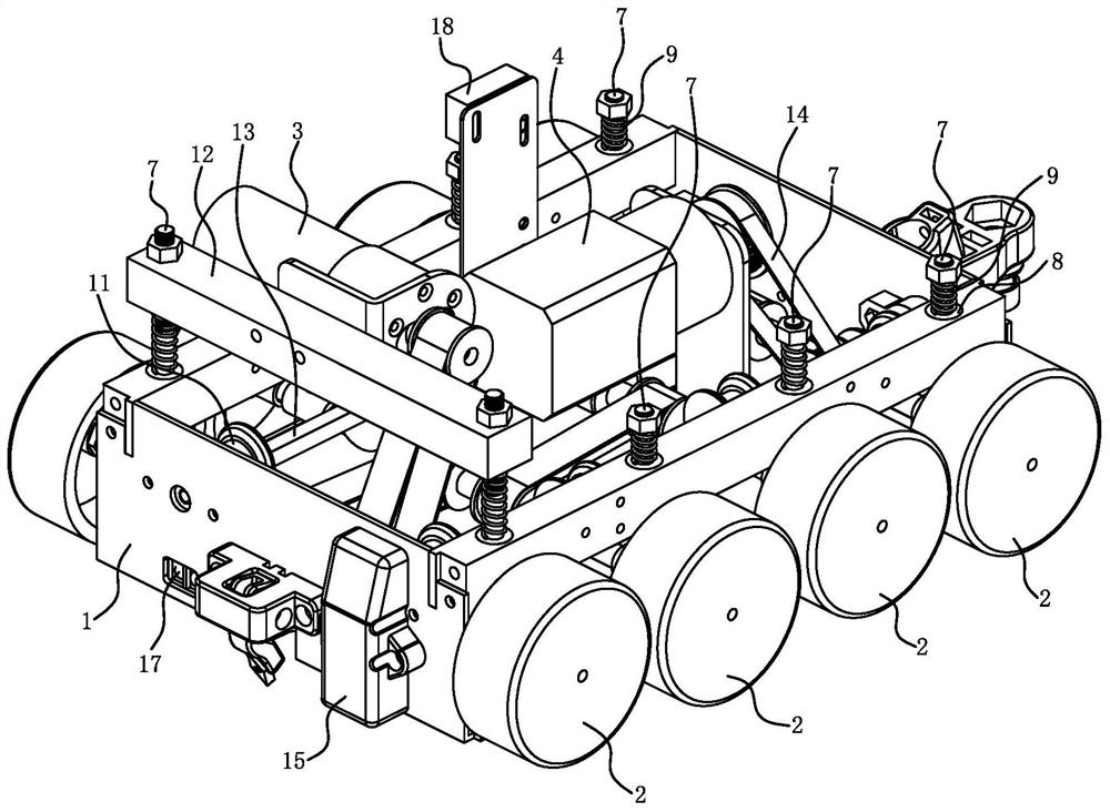
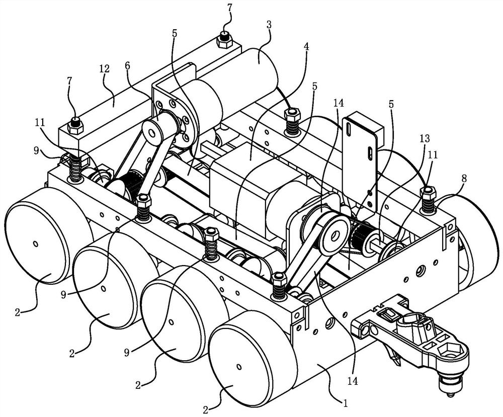
[0027] like Figure 2 to Figure 6 As shown, the walking trolley 100 includes a vehicle body 1 , a control circuit, wheels 2 , a first motor 3 and a second motor 4 . The quantity of wheels 2 is at least 3 groups, and the quantity of wheels 2 given in the accompanying drawings is 4 groups, and multiple groups of wheels 2 are arranged along the traveling direction of the trolley 100 . The wheel 2 includes a wheel shaft 2a and a wheel body 2b installed at both ends of the wheel shaft 2a, and the wheel shafts 2a of two adjacent groups of wheels 2 are connected by a first synchronous belt 5 for transmission. The rotation of the wheels 2 is driven by the first motor 3 , and the main shaft of t...
Embodiment 2
[0038] Embodiment 2: The structure and principle of this embodiment are basically the same as Embodiment 1. The basic similarities are no longer redundantly described, and only the differences are described. The difference is that the wheel surface of the cam 11 is not the same as that of the wheel 2. The wheel shaft 2a relies on each other, but the wheel surface of the cam 11 and the top surface of the guide rod portion 7a in the wheel carrier 7 rely on each other.
Embodiment 3
[0039] Embodiment 3: The structure and principle of this embodiment are basically the same as those of Embodiment 1. The basic similarities are no longer redundantly described, and only the differences are described. The differences are: the reversing member is a screw rod, and the A screw nut is sleeved on the wheel shaft 2a, the screw rod is threadedly connected with the screw nut, and the screw rod is connected with the main shaft of the motor. The rotation of the screw rod forces the screw nut to move axially, thereby realizing the lifting of the wheel 2. When this structure is adopted, the spring 9 can be omitted. .
PUM
 Abstract
Description
Claims
Application Information
 - R&D
- Intellectual Property
- Life Sciences
- Materials
- Tech Scout
- Unparalleled Data Quality
- Higher Quality Content
- 60% Fewer Hallucinations
Browse by: Latest US Patents, China's latest patents, Technical Efficacy Thesaurus, Application Domain, Technology Topic, Popular Technical Reports.
© 2025 PatSnap. All rights reserved.Legal|Privacy policy|Modern Slavery Act Transparency Statement|Sitemap|About US| Contact US: help@patsnap.com


