Check patentability & draft patents in minutes with Patsnap Eureka AI!

Self-bouncing trigger lock body mechanism and lock

A lock body mechanism and lock body technology, applied in building locks, building structures, buildings, etc., can solve problems such as reducing the service life of door locks, and achieve the effect of improving service life

Active Publication Date: 2020-11-17
ZHUHAI UNITECH POWER TECH CO LTD
View PDF4 Cites 1 Cited by
  • Summary
  • Abstract
  • Description
  • Claims
  • Application Information

AI Technical Summary

Problems solved by technology

[0003] The embodiment of the present application provides a self-bounce trigger lock body mechanism to improve the problem that the service life of the door lock is reduced due to the main bolt sticking out before closing the door.

Method used


Image

  • Self-bouncing trigger lock body mechanism and lock
  • Self-bouncing trigger lock body mechanism and lock
  • Self-bouncing trigger lock body mechanism and lock

Examples


Embodiment

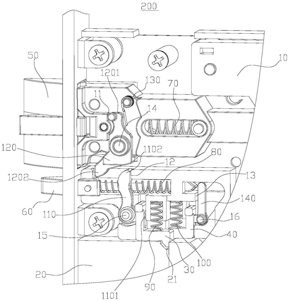
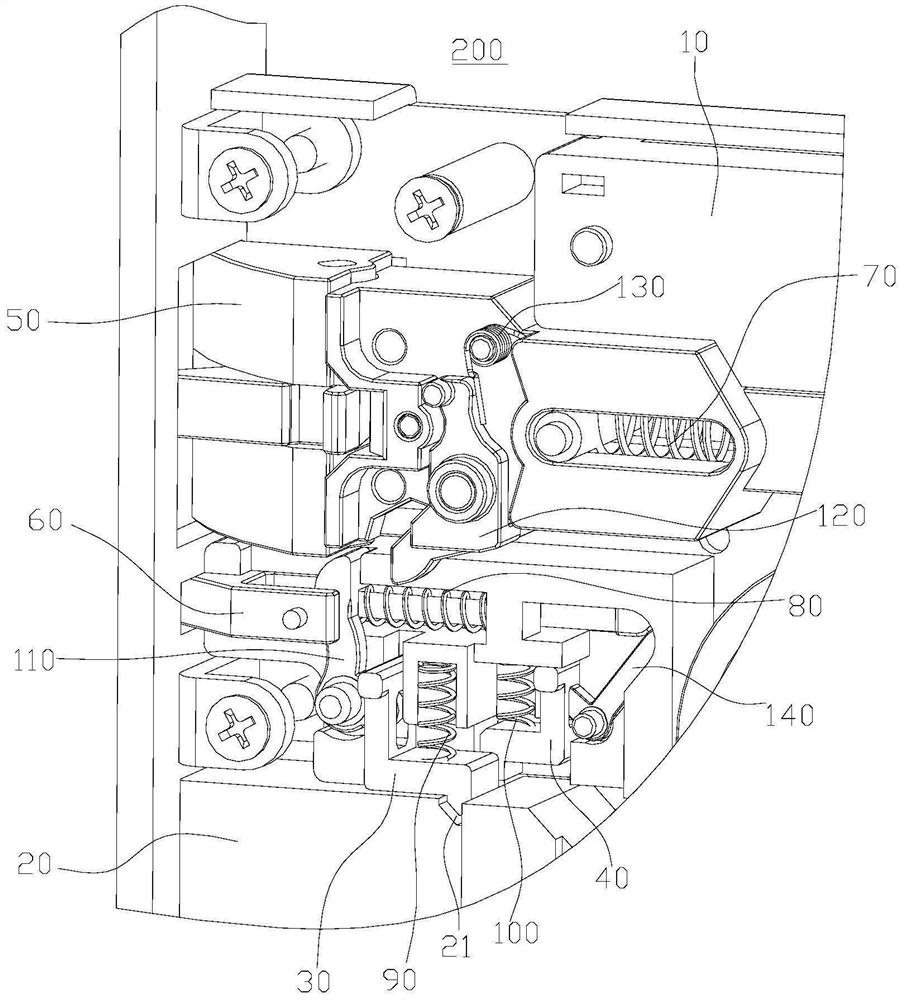
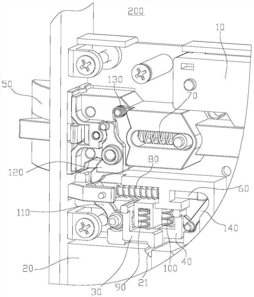
[0059] Such as figure 1 As shown, the embodiment of the present application provides a self-bounce trigger lock body 10 mechanism 200 including a lock body 10 , a main lock tongue 20 , a first locking member 30 , a second locking member 40 , an oblique tongue 50 and a trigger tongue 60 .

[0060] The main bolt 20 has a first position protruding from the lock body 10 and a second position retracting from the lock body 10 . The first locking member 30 is movably disposed on the lock body 10 . The second locking member 40 is movably disposed on the lock body 10 .

[0061] The bolt 50 has a third position protruding from the lock body 10 and a fourth position retracted from the lock body 10. When the bolt 50 is in the third position and the main bolt 20 is in the second position, the first lock Part 30 locks the main bolt 20, and the oblique bolt 50 is used to release the locking of the first locking member 30 to the main bolt 20 at the second position during the process of exte...


PUM


Abstract

The invention provides a self-bouncing trigger lock body mechanism and a lock, and belongs to the technical field of locks. The self-bouncing trigger lock body mechanism comprises a lock body, a mainbolt, a first locking piece, a second locking piece, a latch bolt and a trigger bolt; the main bolt is provided with a first position extending out of the lock body and a second position retracting into the lock body; the latch bolt is provided with a third position extending out of the lock body and a fourth position retracting into the lock body, and the latch bolt is used for releasing lockingof the first locking piece to the main bolt located at the second position in the process that the latch bolt extends out of the fourth position to the third position; and the trigger bolt is providedwith a fifth position extending out of the lock body and a sixth position retracting into the lock body, and the trigger bolt is used for releasing locking of the second locking piece to the main bolt at the second position in the process that the trigger bolt retracts from the fifth position to the sixth position. When a door is closed, the main bolt can be triggered to extend out only by releasing the latch bolt after the latch bolt is pressed in, and it is guaranteed that the main bolt extends out only when the door is closed in place, so that the main bolt is prevented from impacting a door frame in the door closing process, and the service life of the lock is effectively prolonged.

Description

technical field [0001] The present application relates to the technical field of locks, in particular to a self-spring trigger lock body mechanism. Background technique [0002] In the existing door lock, the main bolt is linked with the oblique bolt. After the door is opened, the oblique bolt protrudes from the lock body, and the main bolt retracts to the lock body; when the door is closed, the main bolt returns under the action of the door frame. At the same time, the main deadbolt protrudes outwards. If the door is not closed properly, the main deadbolt stretches out, and the main deadbolt hits the door frame, which reduces the service life of the door lock. Contents of the invention [0003] The embodiment of the present application provides a self-bounce trigger lock body mechanism to solve the problem that the service life of the door lock is reduced due to the main bolt protruding out before the door is fully closed. [0004] In the first aspect, the embodiment of ...

Claims


Application Information

Patent Timeline
IPC IPC(8): E05B63/14E05B15/00E05B15/10E05B15/04E05B63/20
CPCE05B63/146E05B15/00E05B15/102E05B15/04E05B63/20
Inventor 李保福李启平杨绍华温联森
Owner ZHUHAI UNITECH POWER TECH CO LTD
Features
  • R&D
  • Intellectual Property
  • Life Sciences
  • Materials
  • Tech Scout
  • Unparalleled Data Quality
  • Higher Quality Content
  • 60% Fewer Hallucinations
Learn More