Elastic deformation adjusting method for middle frame plate in FCT tester

An adjustment method and elastic deformation technology, applied in the field of FCT testing machines, can solve problems such as subsidence of floating micro-needle block modules, contact problems, and insufficient probe travel.

Active Publication Date: 2020-11-17
P&R MEASUREMENT INC
View PDF10 Cites 3 Cited by
  • Summary
  • Abstract
  • Description
  • Claims
  • Application Information

AI Technical Summary

Problems solved by technology

Due to the excessive force of the upper and lower driving cylinders, the middle frame plate will undergo resilient elastic deformation, or even irreversible plastic deformation
The deformation of the middle frame will cause the needle

Method used


Image

  • Elastic deformation adjusting method for middle frame plate in FCT tester
  • Elastic deformation adjusting method for middle frame plate in FCT tester
  • Elastic deformation adjusting method for middle frame plate in FCT tester

Examples


Example Embodiment

[0083] Example 1: Dynamic adjustment device for elastic deformation of frame plate in FCT testing machine
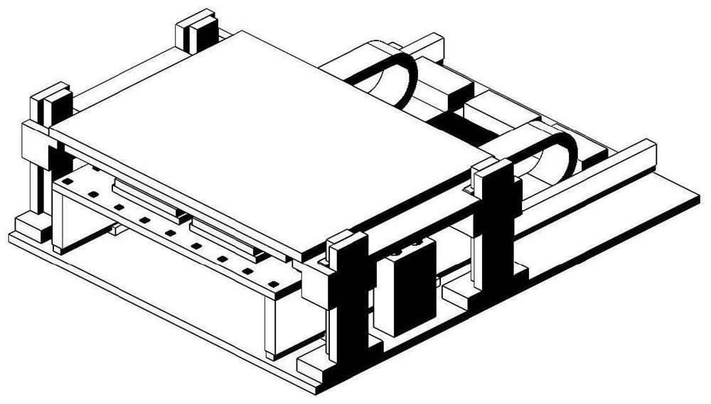
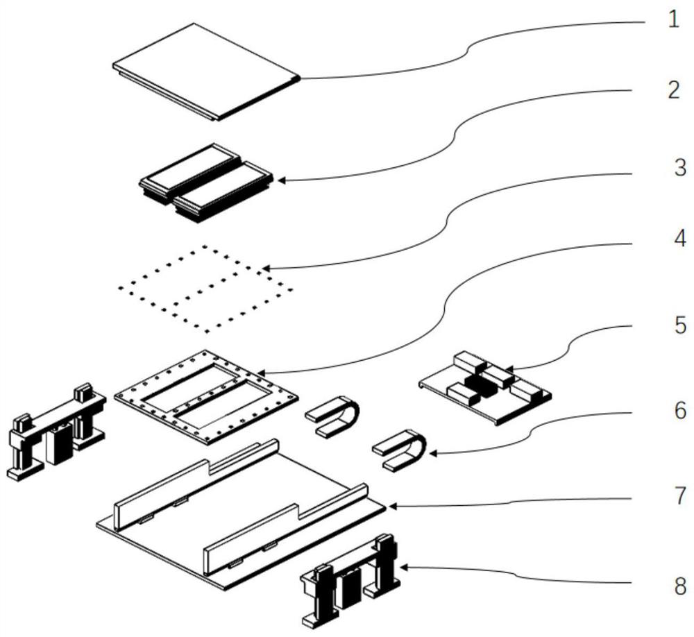
[0084] like Figure 1-2 As shown, the present invention provides a dynamic adjustment device for elastic deformation of a middle frame plate of an FCT testing machine, which mainly consists of the following 8 major parts, including: a pressure plate module 1, a needle carrier module 2, a strain gauge 3, a middle frame Plate module 4, dynamic control module 5, tank chain 6, entry and exit drive module 7 and up and down drive module 8.

[0085] like Figure 3-4 As shown in the figure, the pressing plate module provided by the present invention is used to transmit the force of the upper and lower driving modules to the PCB under test and the carrier board, and reasonably press the stroke of the PCB under test, so that the needle board probe contacts the PCB test point, and realizes the signal Interconnection; the pressure plate module is mainly composed of the following 5...

Example Embodiment

[0101] Embodiment 2: Dynamic adjustment method of elastic deformation of frame plate in FCT testing machine

[0102] like Figure 17 As shown, this embodiment belongs to a real-time dynamic adjustment closed-loop system. Real-time monitoring of the deformation of the middle frame plate, dynamic adjustment of the air pressure of the pressure regulating valve, to prevent the transitional deformation of the middle frame plate, control its reasonable deformation amount, and prevent the probe stroke from being reduced due to the transitional deformation of the middle frame plate. Poor contact has a positive effect on improving the stability of the PCB under test.

[0103] The dynamic adjustment method of the elastic deformation of the middle frame plate of the FCT testing machine (that is, the closed-loop control theory algorithm) is as follows:

[0104] Step 1 Measurement and solution process (stress analysis module):

[0105] First, the strain gauges will be equidistantly past...


PUM


Abstract

The invention relates to an elastic deformation adjusting method for a middle frame plate in an FCT tester. The method comprises the following steps that: S1, real-time data of the deformation of a middle frame plate module is collected through a strain gauge, and is transmitted to a stress analysis module; S2, the stress analysis module converts the deformation data into strain data, identifies the maximum strain value of the middle frame plate, solves the maximum stress value of the middle frame plate, and transmits the data to a data analysis board card in real time; S3, the data analysis board card judges whether the deformation of the middle frame plate module is qualified or not according to the elastic limit stress standard of a middle frame plate material and the actual test stability strain upper limit standard, and judges whether the pressure is increased or decreased; and S4, increasing or decreasing the pressure according to a judgment result of the step S3. According to the invention, the deformation quantity of the middle frame plate can be monitored in real time, the air pressure of a pressure regulating valve is dynamically regulated, and poor contact of a probe caused by excessive deformation of the middle frame plate is prevented.

Description

technical field [0001] The invention relates to the technical field of FCT testing machines, in particular to a method for adjusting elastic deformation of a frame plate in an FCT testing machine. Background technique [0002] With the rapid development of electronic product technology and the increasing requirements for process efficiency and yield, the electronics industry has gradually begun to strengthen the development and optimization of product functional testing equipment while improving the process efficiency of electronic products. Among them, the demand for functional testing of electronic product motherboards is the most urgent. [0003] The structure of the traditional FCT testing machine uses the cylinder to drive the pressure plate to press down, so that the needle carrier plate probe contacts the product test point, and realizes the interactive conduction of product signals. The force of driving the cylinder up and down is transmitted to the needle carrier p...

Claims


Application Information

Patent Timeline
IPC IPC(8): G01R31/28G01B7/16
CPCG01R31/2848G01B7/18
Inventor 莫宗杰杨兴华莫荣键李宇明王飞
Owner P&R MEASUREMENT INC
Why Eureka
Try Eureka