Power grid main equipment polymorphic working condition analysis method and system

An analysis method and technology of main equipment, applied in electrical components, circuit devices, AC network circuits, etc., can solve problems such as the power grid cannot control the reasons for equipment outages, the power grid topology is not refined enough, and the result availability is poor. Effects of Load Flow Calculation Options

Inactive Publication Date: 2020-11-17
CHINA ELECTRIC POWER RES INST +2
View PDF1 Cites 0 Cited by
  • Summary
  • Abstract
  • Description
  • Claims
  • Application Information

AI Technical Summary

Problems solved by technology

At present, the state of equipment such as units, lines, and transformers in the power grid model is only in operation and out of operation, and the state description is single, which cannot satisfy the accurate description of the state of the power grid.
The real-time state of the power grid cannot control the cause of equipment outage, and the availability of equipment cannot be determined in the future state; the power grid topology based on power flow calculation is not refined enough, and the availability of the calculated results is relatively poor
The operation of the power grid is becoming more and more complex, and the lean description of the operating conditions of the power grid equipment plays an important role in the formation of accurate basic data for power grid analysis. The existing analysis methods need to be improved urgently, and new solutions should be found

Method used


Image

  • Power grid main equipment polymorphic working condition analysis method and system
  • Power grid main equipment polymorphic working condition analysis method and system
  • Power grid main equipment polymorphic working condition analysis method and system

Examples


Embodiment approach

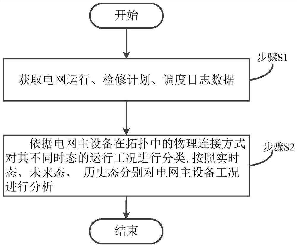
[0045] Such as figure 1 As shown, the present invention provides a method for analyzing the working conditions of the main equipment of the power grid, which specifically includes the following steps: S1, obtaining the actual operation status of the main equipment of the power grid, scheduling logs and maintenance data; S2, according to the physical connection mode of the main equipment of the power grid in the topology Classify its operating conditions in different temporal states, and analyze the main equipment operating conditions of the power grid according to the real-time state, future state, and historical state. The main equipment of the power grid mainly includes units, transformers, busbars, and lines.

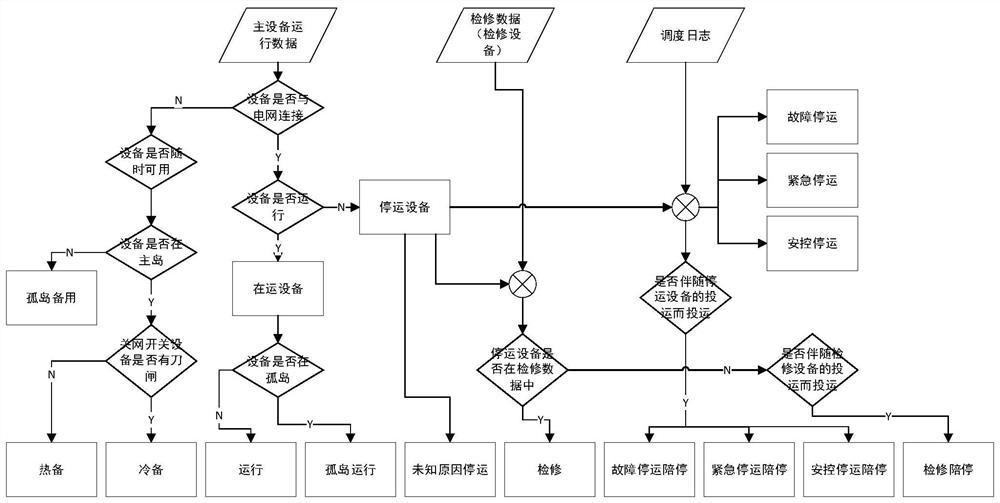
[0046] 1. Analysis of working condition of main equipment in real-time power grid

[0047] see figure 1 and 2As shown, after obtaining the actual operating status of the main equipment of the power grid and the maintenance data, the analysis is carried out in the ...


PUM


Abstract

The invention provides a power grid main equipment working condition analysis method and system. The method comprises the steps that S1, the actual operation condition and maintenance data of power grid main equipment are acquired; S2, according to the physical connection mode of the power grid main equipment in the topology, the actual operation condition of the power grid main equipment and themaintenance data, the operation conditions of the power grid main equipment in different time states are analyzed, wherein the different time states comprise at least one of the following states: a real-time state, a future state and a historical state. Compared with the traditional method for describing the running state of the equipment as available or unavailable, the method has the advantage that the running working conditions of the equipment in a future state, a real-time state and a historical state can be more accurately and visually described. The description can enrich the power flowcalculation selection based on the state of the power grid equipment, so that the power flow calculation is closer to the actual operation condition.

Description

technical field [0001] The invention relates to the technical field of electric power system automation, in particular to a method and method for analyzing multi-state working conditions of main equipment of a power grid. Background technique [0002] With the advancement of power market reform, the security and enforceability of power grids in various regions have put forward new requirements for power grid security management. In the future, with the development of the power spot market, intra-provincial spot transactions will be superimposed on inter-provincial spot transactions, which will bring greater difficulty to power grid management. At present, the state of equipment such as units, lines, and transformers in the power grid model is only in operation and out of operation, and the state description is single, which cannot satisfy the accurate description of the state of the power grid. The real-time state of the power grid cannot control the cause of equipment outa...

Claims


Application Information

Patent Timeline
IPC IPC(8): H02J3/00
CPCH02J3/00H02J2203/10
Inventor 路轶代宇涵李旻张加力蔡帜丁强张国芳郭亮孙毅王金龙胡与非
Owner CHINA ELECTRIC POWER RES INST
Why Eureka
Try Eureka