
High-voltage direct-current line fault detection method, system and device and storage medium

A high-voltage DC, line fault technology, applied in measurement devices, fault locations, information technology support systems, etc., can solve problems such as reducing protection action performance, weakening fault DC current characteristics, and difficult to remove fault DC current, achieving fast backup protection. Effect

Active Publication Date: 2020-11-20
SOUTH CHINA UNIV OF TECH
View PDF8 Cites 6 Cited by
  • Summary
  • Abstract
  • Description
  • Claims
  • Application Information

AI Technical Summary

Problems solved by technology

Although the traveling wave protection operates quickly, its ability to withstand transition resistance is poor. When a high-impedance ground fault occurs, the traveling wave protection is not sensitive enough. It needs the current differential protection as a backup protection to identify the fault DC current. Due to the distribution Due to the influence of capacitive current, DC control characteristics and AC faults outside the inverter side, the traditional current differential protection has the characteristics of low setting value and long delay, which makes the fault DC current exist for a long time in the DC control transient stage and is difficult to remove
The root cause is that the fault DC current is affected by the DC control characteristics, which weakens the fault DC current characteristics to varying degrees, thereby reducing the protection's operating performance.

Method used


Image

  • High-voltage direct-current line fault detection method, system and device and storage medium
  • High-voltage direct-current line fault detection method, system and device and storage medium
  • High-voltage direct-current line fault detection method, system and device and storage medium

Examples


Embodiment Construction

[0049] Embodiments of the present invention are described in detail below, examples of which are shown in the drawings, wherein the same or similar reference numerals designate the same or similar elements or elements having the same or similar functions throughout. The embodiments described below by referring to the figures are exemplary only for explaining the present invention and should not be construed as limiting the present invention. For the step numbers in the following embodiments, it is only set for the convenience of illustration and description, and the order between the steps is not limited in any way. The execution order of each step in the embodiments can be adapted according to the understanding of those skilled in the art sexual adjustment.

[0050] The method and system for detecting a high-voltage direct current line fault according to an embodiment of the present invention will be described in detail below with reference to the accompanying drawings. First...


PUM


Abstract

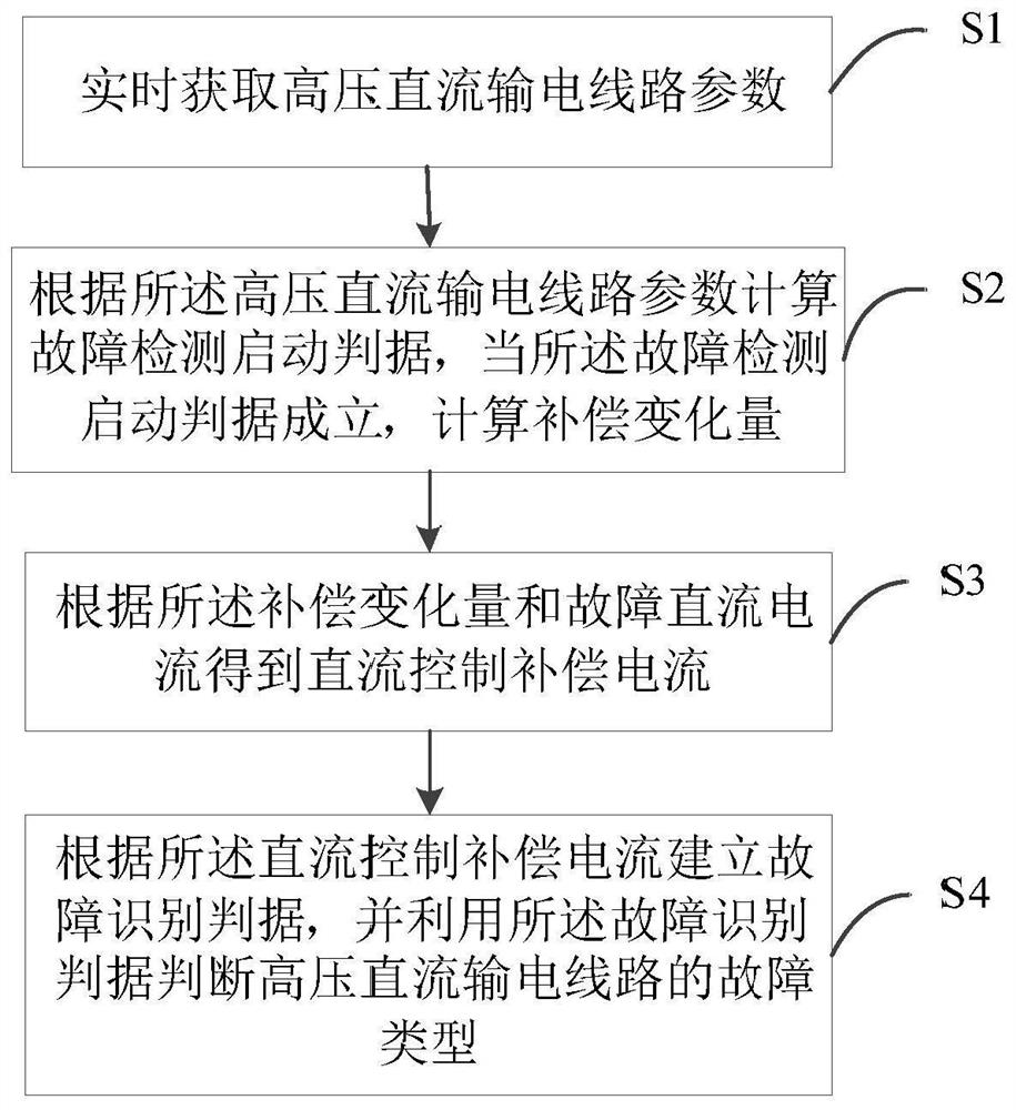
The invention discloses a high-voltage direct-current line fault detection method, system and device. The method comprises the following steps of acquiring parameters of a high-voltage direct-currenttransmission line in real time, calculating a fault detection starting criterion according to the parameters of the high-voltage direct-current transmission line, and calculating a compensation variation when the fault detection starting criterion is established, obtaining a direct current control compensation current according to the compensation variation and the fault direct current, and establishing a fault identification criterion according to the direct-current control compensation current, and judging the fault type of the high-voltage direct-current transmission line by utilizing the fault identification criterion. When the high-voltage direct-current power transmission line breaks down, the influence of the direct-current control characteristic on the fault direct current is compensated through the compensation variation, the characteristic of the fault direct current is highlighted, and therefore the fault of the high-voltage direct-current power transmission line can be accurately detected and recognized, and the method has important significance in rapid backup protection of the direct-current line. The method can be widely applied to the technical field of power systemrelay protection.

Description

technical field [0001] The invention relates to the technical field of relay protection of power systems, in particular to a high-voltage direct current line fault detection method, system, device and storage medium. Background technique [0002] The High Voltage Direct Current (HVDC) system is widely used in modern power systems due to its characteristics of high-power long-distance transmission. At present, in actual engineering, the single-ended protection of fault initial traveling wave is used as the main protection of HVDC lines, including traveling wave protection and differential undervoltage protection. Although the traveling wave protection operates quickly, its ability to withstand transition resistance is poor. When a high-impedance ground fault occurs, the traveling wave protection is not sensitive enough. It needs the current differential protection as a backup protection to identify the fault DC current. Due to the distribution Due to the influence of capacit...

Claims


Application Information

Patent Timeline
Patent Type & Authority Applications(China)
IPC IPC(8): G01R31/08
CPCG01R31/085G01R31/088Y04S10/52
Inventor 李海锋祝新驰顾广坤梁远升
Owner SOUTH CHINA UNIV OF TECH
Learn More