Replaceable modular socket structure

A modular and socket technology, applied in the direction of electrical components, coupling devices, circuits, etc., can solve the problems of inconvenient disassembly and maintenance, and achieve the effects of convenient mating, improved safety performance, and easy disassembly

Active Publication Date: 2020-11-20
DELI GROUP CO LTD
View PDF9 Cites 1 Cited by
  • Summary
  • Abstract
  • Description
  • Claims
  • Application Information

AI Technical Summary

Problems solved by technology

However, if a power module fails, it is extremely inconvenient to disassemble and maintain; and the power module and the power socket are powered on as soon as they are assembled. For children, there are unsafe factors such as wrong power on.

Method used


Image

  • Replaceable modular socket structure
  • Replaceable modular socket structure
  • Replaceable modular socket structure

Examples


Embodiment 1

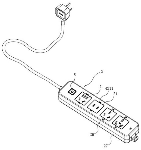
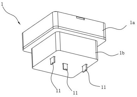
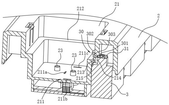
[0033] Such as figure 1 As shown in ~ 7, the replaceable modular socket structure in this embodiment includes a socket assembly 2 and a jack assembly 1, and the upper wall of the socket assembly 2 is provided with a slot 21 for detachable mating of the jack assembly 1, such as image 3 As shown, the bottom of jack assembly 1 has pins 11, correspondingly, as Figure 4 As shown, there is a socket 211 for the pin 11 to pass through on the bottom wall of the slot 21, as Figure 5 As shown, the outer bottom of the slot 21 is provided with an electrical connector 22 arranged corresponding to the socket 211 and used for connecting the pin 11 with the power supply electrical signal.

[0034] Such as image 3 As shown, the above jack assembly 1 has a first part 1a on the upper part and a second part 1b on the lower part, the width of the second part 1b is smaller than the width of the first part 1a so that the cross section of the jack assembly 1 is shaped into a T-shaped structure ...

Embodiment 2

[0043] The difference between this embodiment and embodiment 1 is:

[0044] Such as Figure 8 As shown, on the basis of Embodiment 1, the limit assembly 4 of this embodiment is provided with a chute 4213 connected with the slot 21 on the top wall of the socket assembly 2, and the outer edge of the top of the card 423 is provided with a direction The pinch plate 4231 extending in the chute 4213 has a rib 4232 on the outer edge of the pinch plate 4231 . This structure is conducive to further improving the convenience of operation. When the socket assembly 1 needs to be taken out from the slot 21, the hand clamps the rib 4232 on the buckle plate 4231 and moves it outward along the slide groove 4213, so that it can be easily The buckle 4211 is disengaged from the bayonet 411 , thereby canceling the restriction on the jack assembly 1 .

[0045] The socket assembly 2 is provided with a first elastic member 44 that can keep the card 423 springing toward the inside of the slot 21 al...

Embodiment 3

[0047] The difference between this embodiment and Embodiments 1 and 2 lies in that the structure and operation mode of the limiting components are different.

[0048] Such as Figure 9 , 10 As shown, the limiting assembly in this embodiment includes a bayonet 11a, a bayonet 41a and a drive assembly 4a, the outer wall of the jack assembly 1 is provided with a bayonet 11a, and the side wall of the slot 21 is provided with a corresponding bayonet 11a The notch 211a is arranged, and the socket assembly 2 is provided with a retractable block 41a that is arranged through the notch 211a and is mated with the bayonet 11a to limit when it is inserted into the slot 21 .

[0049] The socket assembly 2 of this embodiment is also provided with a drive assembly 4a for driving the expansion and contraction of the block 41a. Part of the drive assembly 4a is exposed on the outer wall of the socket assembly 2 and always keeps the block 41a extending into the slot 21. the trend of.

[0050] T...


PUM


Abstract

The invention relates to a replaceable modular socket structure, which comprises a socket assembly and a jack assembly, and is characterized in that the socket assembly is internally provided with a travel switch which is positioned outside a slot and is arranged close to a supporting table, and the travel switch is connected between an electric connecting piece and a power supply; a vertically-through notch is formed in the position, close to the outer edge of the supporting table, of the supporting table, and a triggering part of the travel switch is exposed above the notch and can be located on the inner wall face of the slot in a vertically-sliding mode; and the trigger part of the travel switch can slide downwards into the notch under the pressing action of the lower wall surface of the first part of the jack assembly so as to close the travel switch. According to the invention, the jack assembly is detachably inserted into the slot of the socket assembly, and the jack assembly isof a T-shaped structure, so that the jack assembly and the slot are more convenient to insert and match, and are convenient to disassemble and assemble; after plug-in mounting is finished, the firstpart of the T-shaped structure abuts against the triggering part of the travel switch, so that the socket assembly is powered on, the socket assembly is automatically in a power-off state in a non-triggering state, and the safety performance of the socket is improved.

Description

technical field [0001] The invention relates to a replaceable modular socket structure. Background technique [0002] The power socket in the prior art can generally include multiple power modules, but these power modules are generally connected to the same external power supply, and each power module adopts the same national standard. Failure of any power module may cause damage to other power modules, thereby affecting the service life of the entire socket product. However, the power supply standards of different countries may be different. For example, the household electricity in China’s grid is generally 220V, so Chinese electrical appliances are generally suitable for 220V AC, while the household electricity in Japan’s grid is generally 110V, so Japanese electrical appliances are generally Suitable for 110V AC. In some specific occasions, if multiple electrical appliances using the same power socket are applicable to different national standards, the user has power s...

Claims


Application Information

Patent Timeline
Patent Type & Authority Applications(China)
IPC IPC(8): H01R13/514H01R13/703
CPCH01R13/514H01R13/7035
Inventor 周强
Owner DELI GROUP CO LTD
Why Eureka
Try Eureka