Plug of back panel connector, shielding component, shielding plate of component and shielding pin thereof

A technology for backplane connectors and shielding components, which is applied in the direction of connecting parts, protective grounding/shielding devices, connections, electrical components, etc., can solve the problem of affecting the mating performance of backplane connector plugs, unstable axial positioning of shielding pins, The problem of warping and deformation of the shielding sheet is achieved by simplifying the structure and accuracy, firm and precise positioning, and not easy to fall off

Inactive Publication Date: 2009-08-26
CHINA AVIATION OPTICAL-ELECTRICAL TECH CO LTD
View PDF0 Cites 2 Cited by
  • Summary
  • Abstract
  • Description
  • Claims
  • Application Information

AI Technical Summary

Problems solved by technology

Due to the integrated structure of the shielding pin and the shielding sheet in the existing shielding member, the shielding pin can only be stamped together with the shielding sheet during production. In order to ensure the performance of the shielding pin, it is necessary to use high-precision The stamping die is used to stamp the shielding pins to achieve a certain roundness and dimensional accuracy, which results in high production costs and is not conducive to promotion; in addition, when the integrated shielding member is used, the shielding pins themselves have no positioning and anti-retraction structure , it completely depends on the barbs on the wall panels on both sides of the shielding sheet to achieve positioning and stop. Because the shielding sheet is made of very thin boards, the shielding sheet is easily warped and deformed. After the shielding sheet is warped, it will take the shielding pins from the plug female The shielding pin socket of the socket exits, making the axial positioning of the shielding pin in the shielding pin socket of the plug female socket very unstable, which further affects the mating performance of the backplane connector plug

Method used


Image

  • Plug of back panel connector, shielding component, shielding plate of component and shielding pin thereof
  • Plug of back panel connector, shielding component, shielding plate of component and shielding pin thereof
  • Plug of back panel connector, shielding component, shielding plate of component and shielding pin thereof

Examples


Embodiment Construction

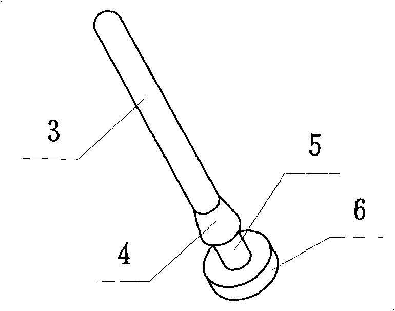
[0017] figure 1 Shown is the shielding pin of the shielding member of the backplane connector plug of the present invention. The shielding pin 3 includes a pin body. A backstop structure 4 is provided on the flange 6 at a set distance, and a neck 5 is formed between the backstop structure 4 and the stop flange 6, and the shielding pin 3 and the shielding piece and the plug in the backplane connector plug When the female seat is connected, the stop flange 6 and the stop structure 4 clamp the shielding pin 3 into the shielding pin socket on the juxtaposed plug socket and the shielding pin hole on the shielding sheet. The neck 5 is located in the shielding pin insertion hole and the shielding pin penetration. The above-mentioned anti-retraction structure 4 is an anti-retraction cone with a gradually larger diameter that is integrally extended from the surface of the pin body to the direction of the stop flange. Barbs instead.

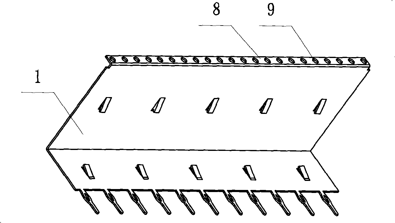
[0018] figure 2 Shown is the shielding piece of...


PUM


Abstract

The invention relates to a plug of a back panel connector, a shielding component, a shielding plate of the component and a shielding pin thereof. The shielding plate and the shielding pin are arranged separated; an outer flange is arranged on an edge of the shielding plate matched with the shielding pin, and is provided with a shielding pin perforation along lengthwise interval; the shielding pin comprises a pin body; the tail end of the pin body is provided with a stop flange; a stopping structure is arranged on a part of the pin body with set distance from the stop flange; a neck part is formed between the stopping structure and the stop flange; the shielding pins are correspondingly clamped in shielding pin jacks on a plug female seat and the shielding pin perforation on the shielding plate which are arranged together in parallel through self stop flange and stopping structure; and neck part of each shielding pin are positioned in corresponding shielding pin jack and shielding pin perforation. The shielding plate and the shielding jacks can be reliably connected with the plug female seat when used, can not be easily separated; and the shielding jacks are processed by machines so as to ensure roundness and dimensional precision of the jacks.

Description

technical field [0001] The invention relates to a backplane connector plug and its shielding component, a shielding piece of the shielding component and its shielding pin. Background technique [0002] The backplane connector is a connector that can achieve lower crosstalk and higher data transmission capabilities. The plug of the connector includes a plug female seat and sub-modules arranged horizontally on the plug female seat. An L-shaped The shielding member is installed on the eaves of the plug socket and the tails of each sub-module through the barbs on the wall panels on both sides. The shielding member is composed of a set of shielding pins and an L-shaped shielding piece. Each shielding pin Arranged on the edge of the wall plate of the shielding sheet that matches with the cornice, and each shielding pin is correspondingly inserted into each shielding pin socket of the plug female seat. Due to the integrated structure of the shielding pin and the shielding sheet in...

Claims


Application Information

Patent Timeline
Patent Type & Authority Applications(China)
IPC IPC(8): H01R13/652H01R12/16H01R12/71
Inventor 张晓光
Owner CHINA AVIATION OPTICAL-ELECTRICAL TECH CO LTD
Why Eureka
Try Eureka