Inertia support grid-connected control system and method based on direct-current capacitor

A technology of DC capacitor and control system, applied in the direction of AC network circuits, electrical components, circuit devices, etc., can solve problems such as the lack of virtual inertial control and the lack of comparison and verification of the effectiveness of virtual inertial control processes.

Pending Publication Date: 2020-11-20
WUHAN INSTITUTE OF TECHNOLOGY
View PDF3 Cites 1 Cited by
  • Summary
  • Abstract
  • Description
  • Claims
  • Application Information

AI Technical Summary

Problems solved by technology

Its shortcoming is that it does not provide a simple and feasible method for the virtual inertia control itself. In addition, it lacks a feasible method for comparing and verifying the effectiveness of the virtual inertia control process.

Method used


Image

  • Inertia support grid-connected control system and method based on direct-current capacitor
  • Inertia support grid-connected control system and method based on direct-current capacitor
  • Inertia support grid-connected control system and method based on direct-current capacitor

Examples


Embodiment Construction

[0074] The principles and features of the present invention will be described below in conjunction with the accompanying drawings, and the examples given are only used to explain the present invention, and are not intended to limit the scope of the present invention.

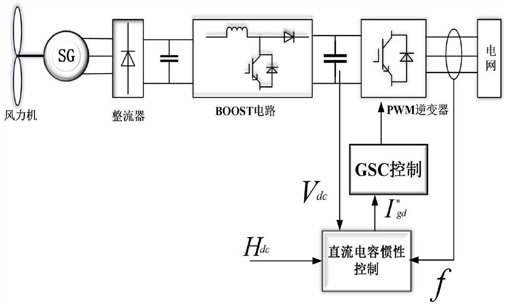
[0075] figure 1 It is a structural block diagram of the system described in the embodiment of the present invention.

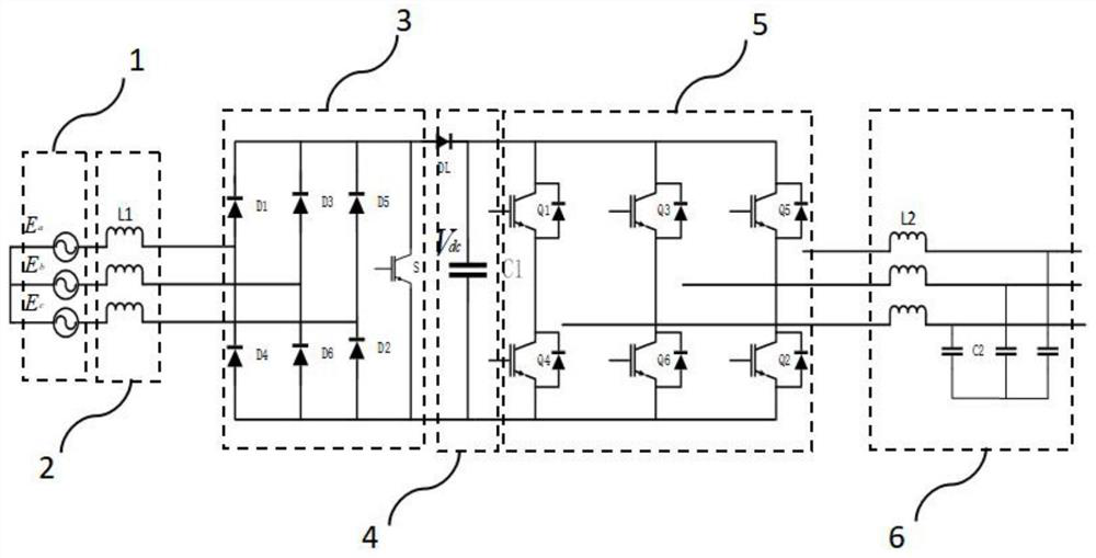
[0076] figure 2 for figure 1 Schematic diagram of the unfolded part of the structure.

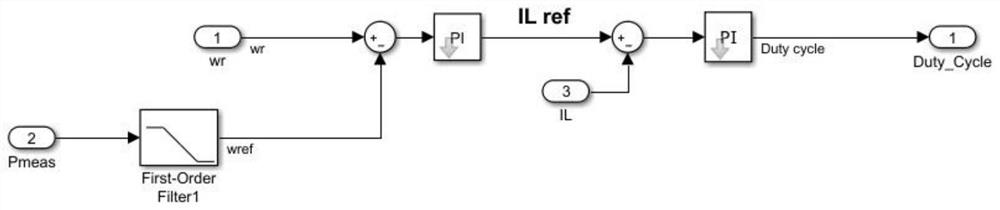
[0077] image 3 for figure 1 Schematic diagram of active power control in the system.

[0078] see figure 1 , 2 As shown, an inertial support grid-connected control system based on DC capacitors, including:

[0079] The synchronous wind generator 1 is used to realize synchronous power generation and output three-phase alternating current;

[0080] The filter inductor 2 is arranged at the output end of each phase of the three-phase alternating current, and is used to filter out the low-order harmonic...


PUM


Abstract

The invention discloses an inertia support grid-connected control system based on a direct-current capacitor. The system comprises a synchronous wind driven generator which is used for achieving synchronous power generation, a filter inductor arranged at an output end of each phase of an three-phase alternating current, a BOOST rectifier arranged on a generator side, a direct-current capacitor arranged at the output end of the BOOST rectifier, an inverter arranged on a power grid side, and an LC filter circuit arranged at a power grid access end, wherein active power of the three-phase alternating current connected to the power grid is a frequency of the power grid; and feedback control among a voltage of the direct-current capacitor, an input current of the inverter, the input current ofthe BOOST rectifier, a stator current of the synchronous wind driven generator and mechanical output power of the synchronous wind driven generator is completed in sequence.

Description

technical field [0001] The invention relates to the field of power electronic control, in particular to a DC capacitor-based inertial support grid-connected control system and method. Background technique [0002] With the development of wind power technology, more and more wind turbines replace traditional synchronous generators, which will inevitably reduce the inertia of the entire system and weaken the frequency response capability of the power generation system. [0003] At present, the typical wind turbine inertia control strategy is to use the method of controlling the kinetic energy of the rotor, and introduce a feedback signal that can reflect the change of the system frequency in the active power control link of the motor side, so that the wind turbine can identify the change of the system frequency according to the feedback signal, and can quickly adjust Output active power. [0004] However, relying on rotor kinetic energy to provide inertia will, to a certain e...

Claims


Application Information

Patent Timeline
Patent Type & Authority Applications(China)
IPC IPC(8): H02J3/38H02J3/48H02J3/24
CPCH02J3/381H02J3/48H02J3/24H02J2203/20H02J2300/28
Inventor 胡俊江卫华胡为兵史博凯李泰
Owner WUHAN INSTITUTE OF TECHNOLOGY
Why Eureka
Try Eureka