A hand-eye calibration system and method for a 3D vision measurement system

A hand-eye calibration and visual measurement technology, which is applied in the field of robot vision sensing, can solve the problems of complicated steps, high professional level requirements of technicians, and large workload and time consumption, so as to reduce workload and working time and achieve high stability , The effect of low professional level requirements

Active Publication Date: 2022-02-15
QUANZHOU HUAZHONG UNIV OF SCI & TECH INST OF MFG +1
View PDF11 Cites 0 Cited by
  • Summary
  • Abstract
  • Description
  • Claims
  • Application Information

AI Technical Summary

Problems solved by technology

It can be seen from the above records that in the prior art, the hand-eye calibration method of the robot has complicated steps, requires a lot of hand-eye calibration workload and time, requires high professional level of technicians, and has poor hand-eye calibration stability.

Method used


Image

  • A hand-eye calibration system and method for a 3D vision measurement system
  • A hand-eye calibration system and method for a 3D vision measurement system
  • A hand-eye calibration system and method for a 3D vision measurement system

Examples


Embodiment 1

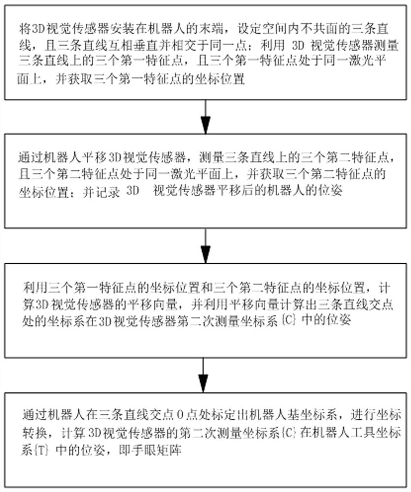
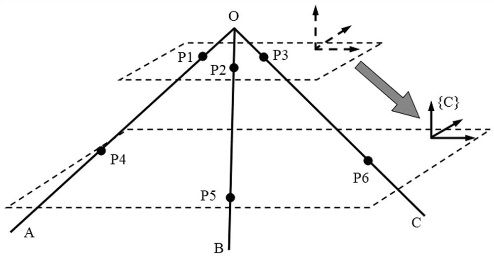
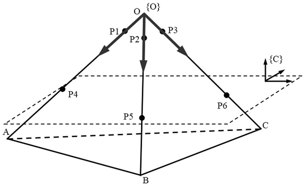
[0062] like Figure 1 to Figure 3 As shown, a hand-eye calibration method for a 3D vision measurement system includes the following steps:

[0063] Step 1. Install the 3D vision sensor on the end of the robot, set three straight lines in the space that are not coplanar, and the three straight lines are perpendicular to each other and intersect at the same point; use the 3D vision sensor to measure the three first feature points on the three straight lines , and the three first feature points are on the same laser plane, and the coordinate positions of the three first feature points are obtained;

[0064] Step 2. Use the robot to translate the 3D vision sensor, measure three second feature points on three straight lines, and the three second feature points are on the same laser plane, and obtain the coordinate positions of the three second feature points; and record the 3D The pose of the robot after the vision sensor is translated;

[0065] Step 3. Utilize the coordinate pos...

Embodiment 2

[0107] like Figure 2 to Figure 4 As shown, a hand-eye calibration system for a 3D vision measurement system, including:

[0108] The first acquisition coordinate module 1, the first acquisition coordinate module 1 installs the 3D vision sensor on the end of the robot, sets three straight lines that are not coplanar in the space, and the three straight lines are perpendicular to each other and intersect at the same point; using 3D vision The sensor measures three first feature points on three straight lines, and the three first feature points are on the same laser plane, and obtains the coordinate positions of the three first feature points;

[0109] The second acquisition coordinate module 2, the first acquisition coordinate module 1 uses the robot to translate the 3D vision sensor, measures three second feature points on three straight lines, and the three second feature points are on the same laser plane, and acquires three The coordinate position of the second feature poi...


PUM


Abstract

The invention relates to a hand-eye calibration system and method for a 3D vision measurement system. The method includes the following steps: installing a 3D vision sensor at the end of a robot, setting three non-coplanar straight lines in the space, and the three straight lines are perpendicular to each other and intersect At the same point; use the 3D vision sensor to measure the three first feature points on the three straight lines to obtain the coordinate positions of the three first feature points; use the robot to translate the 3D vision sensor to measure the three second feature points on the three straight lines, Obtain the coordinate positions of the three second feature points; and record the pose of the robot after the translation of the 3D vision sensor; calculate the translation vector of the 3D vision sensor, and calculate the pose of the intersection of the three straight lines in the second measurement coordinate system; calibration The robot base coordinate system is obtained, and the coordinate transformation is performed to obtain the hand-eye matrix. Compared with the prior art, the present invention has simple steps, reduces workload and working time, and has high hand-eye calibration stability.

Description

technical field [0001] The invention relates to the technical field of robot vision sensing, in particular to a hand-eye calibration system and a calibration method of a 3D vision measurement system. Background technique [0002] In the prior art, such as the application number 201910446270.8, an online hand-eye calibration and grasping pose calculation method for a four-degree-of-freedom 4-R (2-SS) parallel robot stereo vision hand-eye system includes the following steps: Improvement of the error-compensated stereo vision Eye-to-hand model: construct the Eye-to-hand basic model with the camera fixed outside the robot body, and the stereo vision model based on nonlinear distortion in the hand-eye system. At the same time, according to the pose between the cameras The hand-eye model group of each camera and robot in stereo vision is constructed to improve the basic Eye-to-hand model of a single camera; and the robot motion error compensation is performed on the improved Eye-t...

Claims


Application Information

Patent Timeline
Patent Type & Authority Patents(China)
IPC IPC(8): B25J9/02B25J9/08B25J9/16B25J13/08
CPCB25J9/023B25J9/08B25J9/1697B25J13/087
Inventor 李文亮曾恺田陈海亮李佳昌王平江郑康吴梓鸿洪东方苏惠阳何钊滨
Owner QUANZHOU HUAZHONG UNIV OF SCI & TECH INST OF MFG
Why Eureka
Try Eureka