
Multi-signal synchronous transmission system and multi-signal synchronous transmission method

A technology of simultaneous transmission and multiple signals, applied in the field of computers, can solve the problems of increasing transmission channels, changing, increasing the number of connector pins, etc.

Active Publication Date: 2020-11-24
GIGA BYTE TECH CO LTD
View PDF11 Cites 0 Cited by
  • Summary
  • Abstract
  • Description
  • Claims
  • Application Information

AI Technical Summary

Problems solved by technology

However, the transmission of information is limited by standard specifications, and additional transmission channels may be required, for example, increasing the number of pins on the connector, increasing the number of I / O sockets on the circuit board, etc.
However, this requires a change in the overall specification, which may affect the configuration of other components

Method used


Image

  • Multi-signal synchronous transmission system and multi-signal synchronous transmission method
  • Multi-signal synchronous transmission system and multi-signal synchronous transmission method
  • Multi-signal synchronous transmission system and multi-signal synchronous transmission method

Examples


Embodiment Construction

[0038] Below in conjunction with accompanying drawing, structural principle and working principle of the present invention are specifically described:

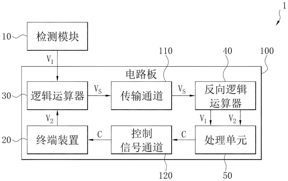
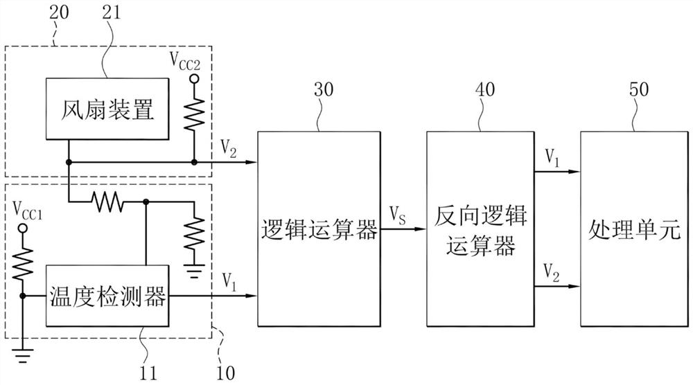
[0039] figure 1 It is a block diagram of a multi-signal synchronous transmission system. Such as figure 1 As shown, the multiple signal synchronous transmission system 1 includes a detection module 10 , a terminal device 20 , a logic operator 30 , an inverse logic operator 40 , and a processing unit 50 . The detection module 10 is electrically connected to the circuit board 100, and generates a first voltage signal V based on the detection value 1 . The terminal device 20 is installed on the circuit board 100, and generates a second voltage signal V based on the operating state of the terminal device 20 2 . The logic operator 30 is arranged on the circuit board 100, electrically connected to the terminal device 20 and the detection module 10, and the logic operator 30 receives the first voltage signal V 1 and the second ...


PUM


Abstract

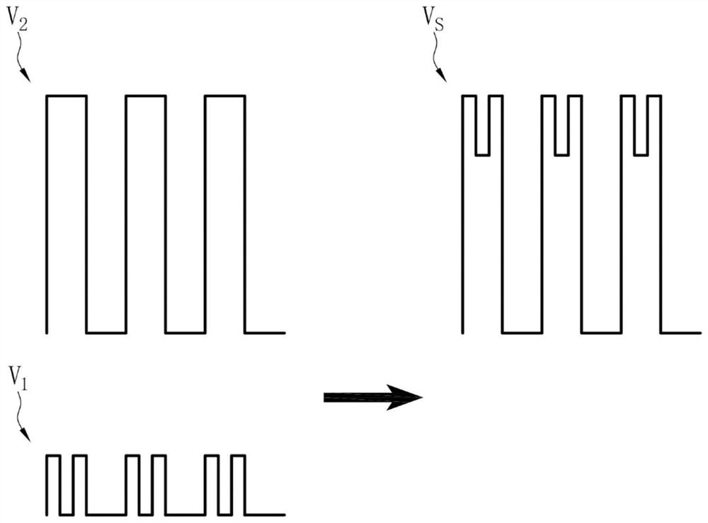
The invention discloses a multi-signal synchronous transmission system and a multi-signal synchronous transmission method. The multi-signal synchronous transmission system comprises a detection module, a terminal device, a logic arithmetic unit, a reverse logic arithmetic unit and a processing unit. The detection module generates a first voltage signal based on the detection value. The terminal device generates a second voltage signal based on its actuation state. The logic arithmetic unit receives the first voltage signal and the second voltage signal, synthesizes the first voltage signal andthe second voltage signal into a synthesized voltage signal through logic operation, and transmits the synthesized voltage signal through a single transmission channel. The reverse logic arithmetic unit receives the synthesized voltage signal through a single transmission channel, and separates the synthesized voltage signal into a first voltage signal and a second voltage signal through reverselogic operation. The processing unit receives and respectively interprets the first voltage signal and the second voltage signal so as to generate corresponding operation instructions.

Description

technical field [0001] The invention relates to the field of computers, in particular to a multi-signal synchronous transmission system and a multi-signal synchronous transmission method. Background technique [0002] Due to the popularization and generalization of computers, the peripheral devices of computers, such as keyboards, fans, mice, etc., will make connectors according to the existing input and output I / O standards, such as fan connectors, COM ports, Printport, RJ45, HDMI, PCIE SLOT, etc. [0003] However, since the computing power of the central processing unit of the computer is greatly improved, correspondingly, additional sensing elements can be provided to judge the state of each component in the computer or the state of the surrounding environment in a more real-time manner. However, the transmission of information is limited by standard specifications, and it may be necessary to increase additional transmission channels, for example, increasing the number o...

Claims


Application Information

Patent Timeline
Patent Type & Authority Applications(China)
IPC IPC(8): G06F13/38G06F11/22G06F1/20
CPCG06F13/382G06F11/221G06F11/2273G06F1/206G06F2200/201
Inventor 简源利孙培华
Owner GIGA BYTE TECH CO LTD
Learn More