Equipment mounting seat for power supply department

A technology for mounting seats and equipment, which is applied to mechanical equipment, lifting devices, lifting frames, etc., and can solve the problems of single height adjustment method and small adjustment range

Inactive Publication Date: 2020-11-27
南京众科汇电气科技有限公司
View PDF1 Cites 4 Cited by
  • Summary
  • Abstract
  • Description
  • Claims
  • Application Information

AI Technical Summary

Problems solved by technology

The device realizes the effective buffering of the power supply equipment after installation. At the same time, through the cooperation between the rotating rod and the supporting rod, it can not only realize the adjustment of the upper and lower heights of the mounting seat, but also form a certain buffering effect, which is very practical. High reliability, but the height adjustment method of the device is relatively simple, and the adjustment range is small, so the device needs to be improved

Method used


Image

  • Equipment mounting seat for power supply department
  • Equipment mounting seat for power supply department
  • Equipment mounting seat for power supply department

Examples


Embodiment 1

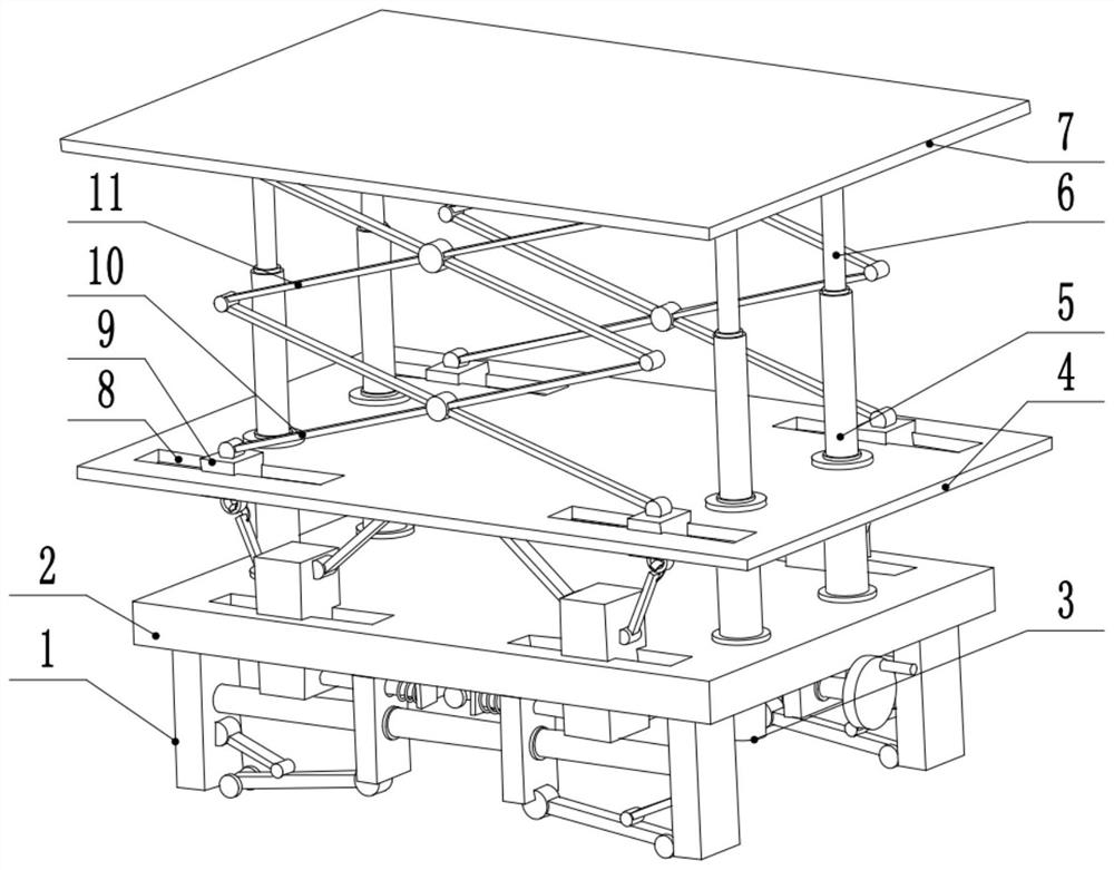
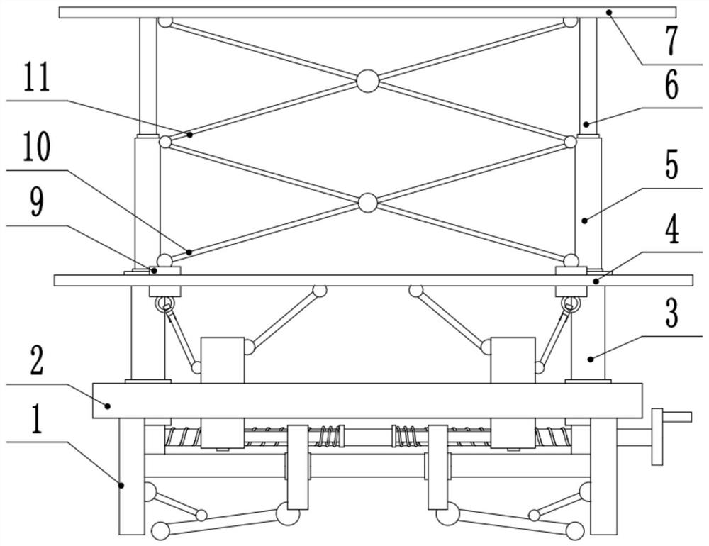
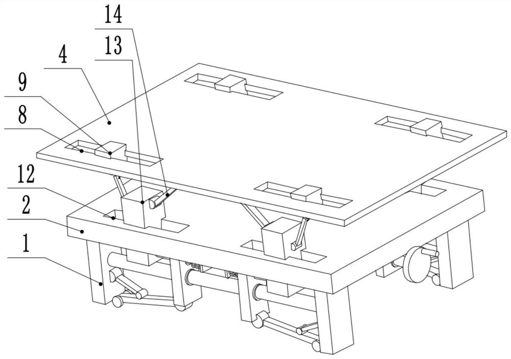
[0028] see Figure 1-5 , a device mounting seat used by a power supply department, including a support plate 4, the left and right sides of the support plate 4 are provided with sliding sleeves 3, the upper part of the sliding sleeve 3 is slidably connected to the lower part of the first sliding rod 5, and the bottom of the first sliding rod 5 The upper part is slidably connected to the bottom of the second sliding rod 6 , the upper end of the second sliding rod 6 is fixedly connected to the lower surface of the supporting plate 7 , and the lower part of the sliding sleeve 3 is slidably connected to the left and right sides of the bottom plate 2 .

[0029] The left and right sides of the lower surface of the base plate 2 are provided with bearing blocks 28, and the middle part of the bearing blocks 28 is rotated to connect the left and right ends of the screw mandrel 27. The left and right sides of the screw mandrel 27 are provided with threads with opposite rotation directions...

Embodiment 2

[0032] see Figure 5 , the other content of this embodiment is the same as that of the first embodiment, except that a spring 22 is provided on the side of the limiting block 23 away from the center of the device. In order to further improve the shock absorption effect of the device, a spring 22 is arranged on the limit block 23, so that the spring 22 can play a shock absorbing effect in the middle when the limit block 23 pulls the third slider 24 to move , so that during the movement of the supporting caster 1 wheel, if the road surface is uneven, the deformation of the spring 22 can be used to offset the vibration of the road surface in time, thereby achieving the effect of shock absorption.

[0033]During the implementation of the present invention, the runner 29 is rotated, and the runner 29 drives the screw mandrel 27 to rotate. Since the left and right sides of the screw mandrel 27 are provided with threads with opposite directions of rotation, when the screw mandrel 27 ...


PUM


Abstract

The invention relates to the technical field of electric power, and discloses an equipment mounting seat for a power supply department. The equipment mounting seat comprises a supporting plate. Sliding sleeves are arranged on the left side and the right side of the supporting plate, the upper portions of the sliding sleeves are slidingly connected with the lower portions of first sliding rods, theupper portions of the first sliding rods are slidingly connected to the lower portions of second sliding rods, the upper ends of the second sliding rods are fixedly connected with the lower surface of a supporting plate, the lower portions of the sliding sleeves are slidingly connected to the left side and the right side of a bottom plate, bearing seats are arranged on the left side and the rightside of the lower surface of the bottom plate, the middles of the bearing seats are rotationally connected with the left end and the right end of a lead screw, the left side and the right side of thelead screw are in threaded connection to the middle of a fixing plate, and the front end and the rear end of the fixing plate are fixedly connected with the middles of first sliding blocks. Accordingto the equipment mounting seat for the power supply department, through the arrangement of pull rods, height adjusting of the device can have two ranges, the range of the maximum height is widened, and the device is more convenient to use.

Description

technical field [0001] The invention relates to the technical field of electric power, in particular to an equipment mounting seat used by a power supply department. Background technique [0002] Power supply refers to the safe, reliable, continuous and qualified sale of electric energy to the majority of power customers through power transmission and distribution devices, so as to meet the needs of customers for economic construction and domestic electricity consumption. Power supply organizations include power supply bureaus and power supply companies. Electric energy is the main energy and driving force of modern industrial production. It is easy to convert from other forms of energy, and easy to convert into other forms of energy for use; its transportation and distribution are simple and economical, and it is easy to control, adjust and measure, which is conducive to the automation of the production process. Therefore, electric energy is widely used in modern industry...

Claims


Application Information

Patent Timeline
Patent Type & Authority Applications(China)
IPC IPC(8): F16M11/38F16M11/42F16F15/067B66F7/06
CPCB66F7/0608B66F7/0625B66F7/0641B66F7/0666F16F15/067F16M11/38F16M11/42
Inventor 李洁
Owner 南京众科汇电气科技有限公司
Why Eureka
Try Eureka