
High-power microwave effect test device for micro multi-rotor unmanned aerial vehicle

A multi-rotor unmanned aerial vehicle and high-power microwave technology, which is used in aircraft component testing and other directions, can solve problems such as inability to simulate the flight state of unmanned aerial vehicles, achieve high-precision microwave power density control, avoid falling risks, and improve safety factors Effect

Active Publication Date: 2020-12-01
INST OF APPLIED ELECTRONICS CHINA ACAD OF ENG PHYSICS
View PDF6 Cites 8 Cited by
  • Summary
  • Abstract
  • Description
  • Claims
  • Application Information

AI Technical Summary

Problems solved by technology

[0006] The purpose of the present invention is, in order to overcome the defect of prior art, provide a kind of high-power microwave effect test device of miniature multi-rotor unmanned aerial vehicle, solve the high In the power microwave effect test, it is impossible to simulate the flight state of the UAV, monitor the UAV effect in multiple directions, and accurately control the power density of the environment field where the UAV is located.

Method used


Image

  • High-power microwave effect test device for micro multi-rotor unmanned aerial vehicle

Examples


Embodiment 1

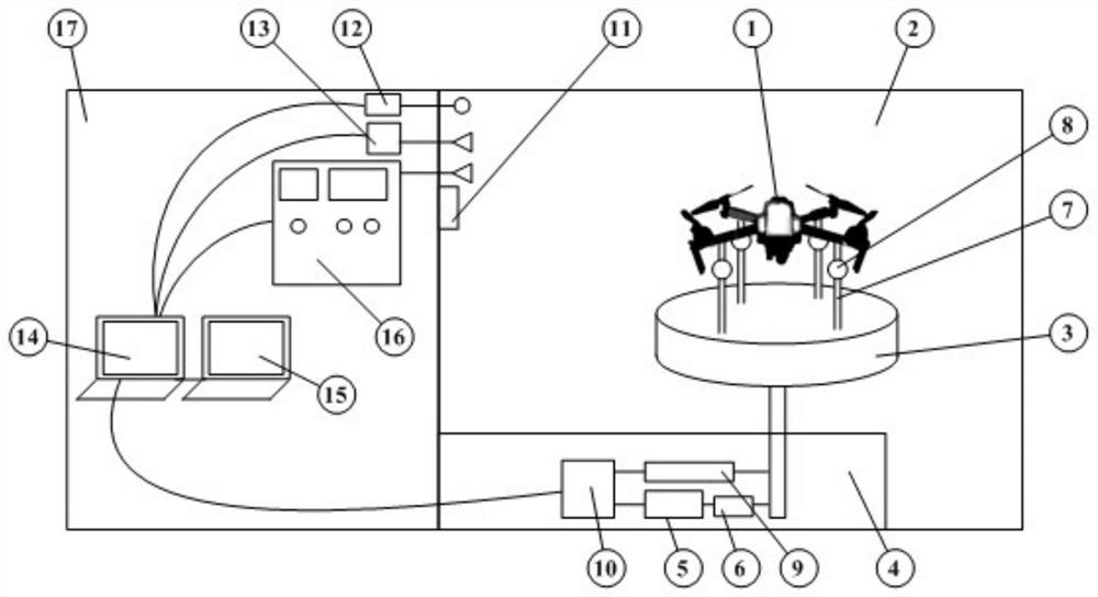
[0037] refer to figure 1 As shown, the present invention discloses a high-power microwave effect test device for a miniature multi-rotor unmanned aerial vehicle. Device control system 14 , ground workstation 15 , HPM irradiation environment generation module 16 and electromagnetic shielding room 17 .

[0038] Preferably, the simulated flight platform is used to provide a simulated real flight environment for the UAV 1 to be tested. The microwave anechoic chamber 2 is used to provide a test place. The video monitoring module 12 is used to complete the attitude monitoring of the UAV 1 .

[0039] The global positioning signal generating module 13 is configured to generate a positioning signal for a set position and a set altitude for the UAV 1 to be tested. The ground workstation 15 is used to control the UAV 1 . The HPM radiation environment generating module 16 is configured to apply an HPM radiation field with set parameters to the UAV 1 to be tested. Wherein, HPM refers ...


PUM


Abstract

The invention discloses a high-power microwave effect test device for a micro multi-rotor unmanned aerial vehicle. The test device at least comprises a simulation flight platform, a video monitoring module, a global positioning signal generation module, an HPM irradiation environment generation module and a device control system. The simulation flight platform at least comprises a mechanical rotating platform, a driving unit, a supporting rod and a supporting induction control unit. The video monitoring module is configured to monitor a to-be-tested unmanned aerial vehicle, and the global positioning signal generation module is configured to generate a positioning signal with a set position and a set height for the to-be-tested unmanned aerial vehicle; the HPM irradiation environment generation module is configured to apply an HPM radiation field with set parameters to the to-be-tested unmanned aerial vehicle. With the structural design of the test device, the problems that the flightstate of the unmanned aerial vehicle cannot be simulated, the effect of the unmanned aerial vehicle cannot be monitored in multiple directions and the power density of the environment field where theunmanned aerial vehicle is located cannot be accurately controlled in the existing micro multi-rotor unmanned aerial vehicle high-power microwave effect test are solved.

Description

technical field [0001] The invention belongs to the technical field of high-power microwave utilization, and in particular relates to a high-power microwave effect test device for a miniature multi-rotor unmanned aerial vehicle. Background technique [0002] With the continuous development of intelligent unmanned technology, the miniaturization and intelligence of drones continue to increase, making them widely used in many fields such as photography, terrain exploration, field rescue, and light shows. However, during the working process of UAVs, crashes caused by the influence of the external electromagnetic environment occur from time to time, especially for micro-sized UAVs, whose electronic information systems are sophisticated, highly integrated, and highly electromagnetically sensitive. Due to cost considerations, man-machine lacks redundant design, and it is difficult to withstand the impact of high-power microwave pulses. Therefore, it is of great significance to ca...

Claims


Application Information

Patent Timeline
Patent Type & Authority Applications(China)
IPC IPC(8): B64F5/60
CPCB64F5/60
Inventor 冯溪溪袁欢戈弋赵刚陈朝阳赵景涛陈自东刘忠蔡武川
Owner INST OF APPLIED ELECTRONICS CHINA ACAD OF ENG PHYSICS
Learn More