Low voltage contact assembly

A contact assembly, low-voltage technology, applied in the direction of contacts, contact meshing, electrical components, etc., can solve problems such as current imbalance, uneven pressure distribution, etc.

Pending Publication Date: 2020-12-01
ABB (SCHWEIZ) AG
View PDF8 Cites 0 Cited by
  • Summary
  • Abstract
  • Description
  • Claims
  • Application Information

AI Technical Summary

Problems solved by technology

Therefore, in this case, as indicated by the arrow 510, the pressure applied by the pressing rod 501 is distributed unevenly and the current also flows between the movable contacts 711, 721 and the fixed contact 51 in an unbalanced manner.

Method used


Image

  • Low voltage contact assembly
  • Low voltage contact assembly
  • Low voltage contact assembly

Examples


Embodiment Construction

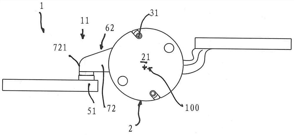
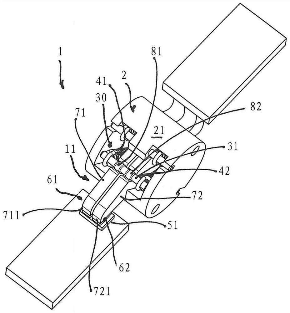
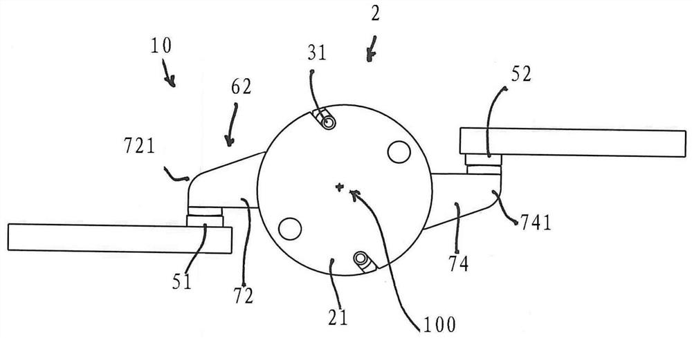
[0047] Referring to the figures, the low voltage contact assembly 1 , 10 of the present invention comprises in its more general definition a rotary support 2 having a body 21 adapted to rotate about a rotation axis 100 .

[0048] exist figure 1 and figure 2 In the single interrupt configuration, the main body 21 supports at least a first pair of movable contacts 11 that can be coupled / disconnected with corresponding first fixed contacts 51 by rotating around the rotation axis 100 open.

[0049] In particular, the first pair of movable contacts 11 generally comprises a first movable contact 61 and a second movable contact 62 , both housed in said rotary support 2 . According to known embodiments, the first movable contact 61 and the second movable contact 62 have corresponding first and second elongated contact bodies 71 and 72, the first elongated contact body 71 And the second elongated contact body 72 has contact ends 711 , 721 protruding from the rotary support 2 .

...


PUM


Abstract

A low voltage contact assembly comprising a rotating support having a body adapted to rotate around a rotation axis and supporting at least a first couple of movable contacts that can be coupled to /uncoupled from corresponding first fixed contacts by rotation around said rotation axis, said first couple of movable contacts comprising a first and a second movable contacts housed in said rotatingsupport and each having a corresponding first and second elongated contact body with a contact end protruding from said rotating support, said first and second elongated contact bodies lying parallelto each other in a rotation plane substantially perpendicular to said rotation axis. The low voltage assembly being further comprises a pressure exerting device having a pressing bar operatively coupled to said first and second elongated contact body and transversally placed with respect to said rotation plane of said first and second elongated contact bodies, and a first and a second elastic elements positioned at opposite ends of said pressing bar, said pressing bar further comprising a first and a second operating surface each comprising a corresponding first and second pressing surface protruding from said pressing bar and respectively acting on said first and second elongated contact body.

Description

technical field [0001] The invention relates to a low-voltage contact assembly for a low-voltage switchgear, in particular for a low-voltage circuit breaker. More specifically, the present invention relates to a low voltage contact assembly having a dual movable contact arrangement. Background technique [0002] It is known in the low-voltage field that switching devices (especially circuit breakers) are usually provided with a contact assembly comprising a movable contact and a fixed contact capable of Connect and disconnect from each other. The low-voltage switchgear of known art also comprises control means which cause the relative movement of said movable contacts with respect to the fixed contacts so that they can assume at least a first coupled position (circuit closed) and a second disengaged position (circuit open). [0003] It is known in the low voltage field that for certain applications it is desirable to have double movable contacts to split the current into ...

Claims


Application Information

Patent Timeline
Patent Type & Authority Applications(China)
IPC IPC(8): H01H73/04H01H1/58
CPCH01H1/2041H01H1/34H01H1/50H01H71/1027H01H73/04H01H1/58H01H1/226H01H1/5822H01H1/221H01H2001/223
Inventor M·博恩凡蒂M·吉斯洛蒂M·塞罗尼
Owner ABB (SCHWEIZ) AG
Why Eureka
Try Eureka