Unmanned aerial vehicle cooperative photography method and device, computer equipment and storage medium

A technology of unmanned aerial vehicle and shooting position, applied in the field of computer and unmanned aerial vehicle, it can solve the problems of unable to shoot moving objects, unable to pre-determine shooting route, unsuitable for aerial photography of complex dynamic scenes, etc., to achieve the effect of effective shooting

Active Publication Date: 2020-12-01
MOUTONG SCI & TECH CO LTD
View PDF6 Cites 3 Cited by
  • Summary
  • Abstract
  • Description
  • Claims
  • Application Information

AI Technical Summary

Problems solved by technology

[0003] However, the traditional UAV automatic aerial photography method mainly uses a fixed and pre-generated aerial photography route for the aerial photography of the overall fixed scene. If the objects in the scene do not move or the moving objects are not the focus of shooting, it is impossible to target the moving objects. to shoot
For complex dynamic scenes, it is often impossible to pre-determine the shooting route and require real-time targeted shooting of moving objects
Therefore, there is a problem that traditional methods are not suitable for aerial photography of complex dynamic scenes

Method used


Image

  • Unmanned aerial vehicle cooperative photography method and device, computer equipment and storage medium
  • Unmanned aerial vehicle cooperative photography method and device, computer equipment and storage medium
  • Unmanned aerial vehicle cooperative photography method and device, computer equipment and storage medium

Examples


Embodiment Construction

[0028] In order to make the purpose, technical solution and advantages of the present application clearer, the present application will be further described in detail below in conjunction with the accompanying drawings and embodiments. It should be understood that the specific embodiments described here are only used to explain the present application, and are not intended to limit the present application.

[0029] The UAV cooperative photography method provided in this application can be applied in the following application environments. Among them, the computer equipment communicates with multiple drones through the network. Wherein, the computer equipment may be a terminal or a server. Terminals can be, but are not limited to, various personal computers, notebook computers, smart phones, tablet computers, and portable wearable devices, and servers can be implemented by independent servers or server clusters composed of multiple servers.

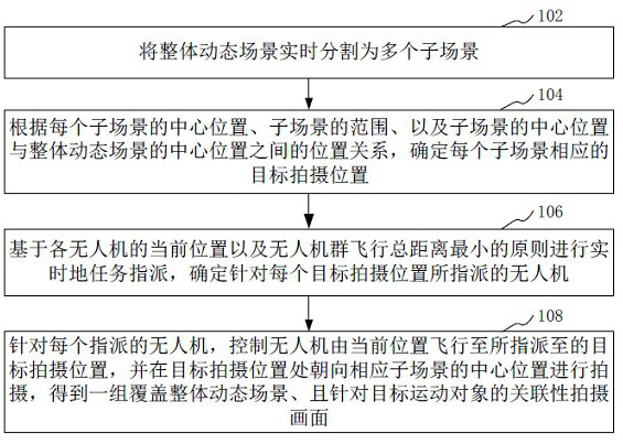
[0030] In one embodiment, such as...


PUM


Abstract

The invention relates to an unmanned aerial vehicle cooperative photography method and device, computer equipment and a storage medium. The method comprises the following steps: segmenting an overalldynamic scene into a plurality of sub-scenes in real time; determining a target shooting position corresponding to each sub-scene according to the central position of each sub-scene, the range of eachsub-scene and the position relationship between the central position of each sub-scene and the central position of the overall dynamic scene; performing real-time task assignment based on the currentposition of each unmanned aerial vehicle and the principle that the total flight distance of the unmanned aerial vehicle group is minimum, and determining the unmanned aerial vehicle assigned for each target shooting position; and for each assigned unmanned aerial vehicle, controlling the unmanned aerial vehicle to fly from the current position to the assigned target shooting position, and shooting towards the central position of the corresponding sub-scene at the target shooting position to obtain a group of associated shooting pictures covering the overall dynamic scene and aiming at the target moving object. The scheme can be suitable for complex dynamic scene aerial photography.

Description

technical field [0001] The present application relates to the field of computer technology and the field of drone technology, in particular to a method, device, computer equipment and storage medium for cooperative photography of drones. Background technique [0002] In recent years, UAV technology has been widely used and developed rapidly. People are increasingly using UAVs to shoot various scenes, especially for fixed scenes such as urban street scenes and landscapes. However, people's demand for the use of drones is not limited to the shooting of fixed static scenes, and they often want to use drones to take aerial photos of some complex dynamic scenes. For example, a multi-person ball game or a venue for events, etc., are relatively complex dynamic scenes involving moving objects. [0003] However, the traditional UAV automatic aerial photography method mainly uses a fixed and pre-generated aerial photography route for the aerial photography of the overall fixed scene....

Claims


Application Information

Patent Timeline
Patent Type & Authority Applications(China)
IPC IPC(8): H04N5/232G06K9/62
CPCH04N23/80G06F18/23213
Inventor 黄惠
Owner MOUTONG SCI & TECH CO LTD
Why Eureka
Try Eureka