A gate device for water conservancy
A gate and water conservancy technology, applied in water conservancy projects, cleaning methods using tools, cleaning methods and utensils, etc., can solve problems such as laborious inefficiency, potential safety hazards of flood disasters, and inability to timely and accurately perceive the height of the water level. Achieve the effect of prolonging the service life and avoiding a large amount of rust
- Summary
- Abstract
- Description
- Claims
- Application Information
AI Technical Summary
Problems solved by technology
Method used
Image
Examples
Embodiment 1
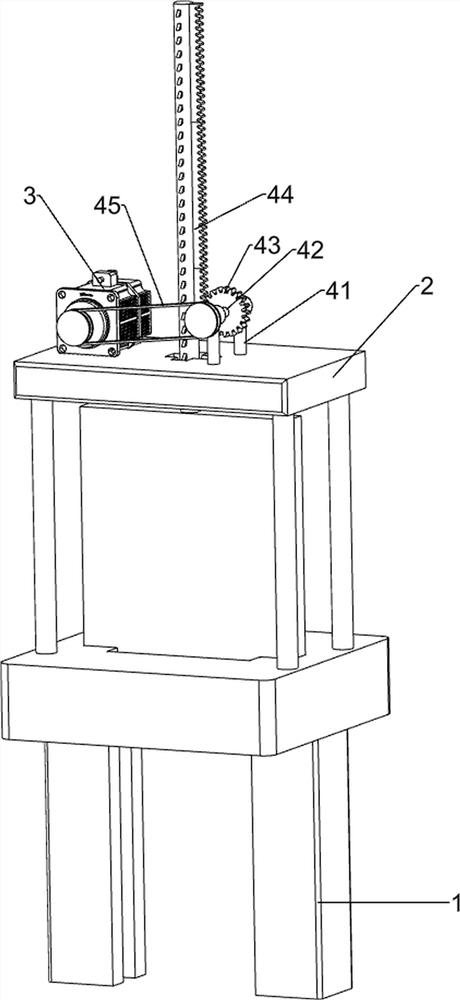
[0022] A gate device for water conservancy, such as figure 1 As shown, it includes a main frame 1, a support frame 2, a motor 3 and a baffle mechanism 4. The main frame 1 is provided with a support frame 2, the left side of the support frame 2 is equipped with a motor 3, and the middle of the support frame 2 is provided with a stopper. Plate Mechanism4.
[0023] When it is necessary to discharge floods and irrigate the surrounding farmland, the person in charge of the water conservancy work starts the motor 3, and the output shaft of the motor 3 drives the baffle mechanism 4 to move upward. When it moves to a suitable height, the motor 3 is turned off, and the stored water flows into In the surrounding farmland, when the water level reaches a certain height, the reverse rotation of the motor is artificially controlled, so that the baffle mechanism 4 moves downward, thereby blocking the water flow.
Embodiment 2
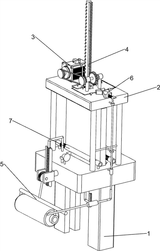
[0025] On the basis of Example 1, such as figure 2 As shown, the baffle mechanism 4 includes a first column sleeve 41, a first rotating shaft 42, a first gear 43, a gate 44 and a first belt device 45, and the top of the support frame 2 is symmetrically provided with the first column sleeve 41, the first A first rotating shaft 42 is rotatably provided between the column sleeves 41, a first gear 43 is arranged in the middle of the first rotating shaft 42, a gate 44 is arranged on the support frame 2 between the motor 3 and the first gear 43, and the first gear 43 It meshes with the side wall of the gate 44 , the first gear 43 meshes with the gate 44 , and the output shaft of the motor 3 is connected to the front side of the first rotating shaft 42 with a first belt device 45 in transmission type.
[0026] The output shaft of the motor 3 drives the first belt device 45 to drive, thereby driving the first rotating shaft 42 to rotate, and the first rotating shaft 42 drives the fir...
Embodiment 3
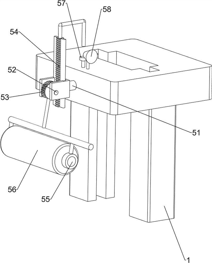
[0028] On the basis of Example 2, such as Figure 3-6 Shown, also comprise early-warning mechanism 5, main frame 1 top front side is provided with early-warning mechanism 5, and early-warning mechanism 5 comprises fixed seat 51, second rotating shaft 52, second spur gear 53, rack 54, the 3rd rotating shaft 55 , floating drum 56, alarm touch switch 57 and alarm horn 58, main frame 1 front wall upper part is provided with fixed seat 51, and fixed seat 51 front side rotation type is provided with second rotating shaft 52, and the middle of second rotating shaft 52 is provided with second rotating shaft. Spur gear 53, fixed seat 51 rear side inner wall sliding type is provided with rack 54, and tooth rack 54 is meshed with the second spur gear 53, and the outside of second spur gear 53 is provided with the 3rd rotating shaft 55, and the rotating type is arranged on the 3rd rotating shaft 55. There is a buoy 56, the left side of the main frame 1 is provided with an alarm touch swit...
PUM
 Abstract
Description
Claims
Application Information
 - R&D
- Intellectual Property
- Life Sciences
- Materials
- Tech Scout
- Unparalleled Data Quality
- Higher Quality Content
- 60% Fewer Hallucinations
Browse by: Latest US Patents, China's latest patents, Technical Efficacy Thesaurus, Application Domain, Technology Topic, Popular Technical Reports.
© 2025 PatSnap. All rights reserved.Legal|Privacy policy|Modern Slavery Act Transparency Statement|Sitemap|About US| Contact US: help@patsnap.com


