Dynamically placing resources within a graphical user interface

a dynamic placement and user interface technology, applied in the field of computer programming, can solve the problems of wasting valuable time and resources and the “forth” between graphic designers and software developers wastes valuable time and resources for those involved, and achieves the effect of eliminating the dependency of graphical designers and reducing the amount of preparation tim

Active Publication Date: 2009-12-01
ESCHER GROUP
View PDF13 Cites 2 Cited by
  • Summary
  • Abstract
  • Description
  • Claims
  • Application Information

AI Technical Summary

Benefits of technology

[0014]Advantageously, the novel technique dynamically places resources within a GUI. By encoding the position information within the filename of the resource, the novel technique reduces the steps involved between graphic designers and software developers for laying out the resources within the GUI. Accordingly, valuable preparation time in generating the GUI is saved for both the graphic designers and software developers. Allowing the graphical designers (or anyone) to dynamically change the position of a resource within the GUI simply by changing the resource's filename thus eliminates the graphical designers' dependency upon the software developers' re-coding the placement of the resources.

Problems solved by technology

One problem with the above arrangement between the software developer and the graphic designer is that the graphic designers often change the layout of the GUI during development (and afterward), e.g., to move resources from one location to another (and / or to change the image associated with the resource).
This “back-and-forth” between the graphic designer and software developer wastes valuable time and resources for those involved.
As mentioned, the graphic designer may often change the position of a resource during development of the GUI, and the back-and-forth between the designer and the software developer of steps 130 through 145 becomes a major inefficiency in the development process.

Method used


Image

  • Dynamically placing resources within a graphical user interface
  • Dynamically placing resources within a graphical user interface
  • Dynamically placing resources within a graphical user interface

Examples


Embodiment Construction

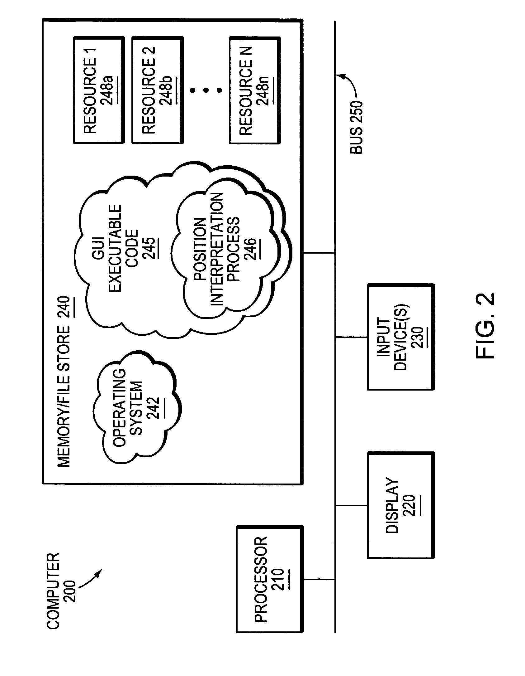
[0026]FIG. 2 is a schematic block diagram of an exemplary computer 200 that may be advantageously used with the present invention, such as a personal computer (PC), personal digital assistant (PDA), other handheld devices, etc. The computer comprises a processor 210, a display 220, one or more input devices 230, and a memory 240 (e.g., a file store) interconnected by a system bus 250. The display 220 may be used to display images or graphics associated with a Graphical User Interface (GUI) in accordance with the present invention. Input devices 230 allow a user to interact with the computer 200, and may comprise, inter alia, a keyboard, a mouse, a touch screen (e.g., with a stylus), which may be embodied as display 220, etc. Input devices 230 may also comprise communication ports (e.g., serial / parallel ports, a universal serial bus, USB, etc.) configured to receive data from external sources, such as, e.g., pre-programmed GUIs that have been developed on one or more other computers ...


PUM


Abstract

A technique dynamically places resources within a graphical user interface (GUI). According to the novel technique, a resource (e.g., an image of the resource) of the GUI is assigned a filename (e.g., by a graphic designer) having position information encoded therein. For example, a resource with coordinates of 50 pixels in the “X” direction (“50X”) and 50 pixels in the “Y” direction (“50Y”) may be represented with a corresponding filename: “resourcename_50×50.jpg.” Software code that displays the GUI (e.g., maintained by a software developer) may then dynamically interpret the filename to parse out the position information (e.g., 50X and 50Y). The software code then places the resource in a position within the GUI according to the position information. Subsequently, changing the position information encoded within the filename (e.g., by the graphic designer) changes the position of the resource in the GUI (e.g., renaming the resource to “resourcename_100×50.jpg” replaces the resource at 100X and 50Y).

Description

BACKGROUND OF THE INVENTION[0001]1. Field of the Invention[0002]This invention relates generally to computer programming, and more particularly, to dynamically placing resources within a graphical user interface (GUI).[0003]2. Background Information[0004]Generally, computers have had many different uses and / or purposes, such as for performing calculations, word processing, data storage, etc. Computers normally have a means for processing data, a means for displaying data, and means for inputting data. An example computer may take the form of a personal computer (PC) or other device, such as a peripheral device (e.g., handheld devices, etc.). Until recently, people have interfaced with computers primarily utilizing text-based interfaces, or Command Line Interfaces (CLIs). In a CLI, a user inputs text-based commands to the computer based on one or more programming languages (e.g., a disk operating system, or DOS language, etc.) using a keyboard. The computer then responds according to...

Claims


Application Information

Patent Timeline
Patent Type & Authority Patents(United States)
IPC IPC(8): G06F3/00
CPCG06F9/4443G06F9/451
Inventor LUDMANN, SANDOR
Owner ESCHER GROUP
Why Eureka
Try Eureka