Spatial light modulation device, spatial light modulation method, and optical switch

A technology of spatial light modulation and light modulation element, applied in the field of optical communication, can solve the problems of large occupation of computing resources, high occupation bandwidth, large physical area, etc.

Active Publication Date: 2021-02-26
南京芯视元电子有限公司
View PDF4 Cites 0 Cited by
  • Summary
  • Abstract
  • Description
  • Claims
  • Application Information

AI Technical Summary

Problems solved by technology

[0004] In the prior art, for the processing of image signal transmission and wavelength assignment, it is first necessary to receive the pre-generated image source information, and then modulate the image source information. Since the image source information itself carries a lot of data, the amount of data transmission is large. , occupies a high bandwidth, occupies a large amount of computing resources, and has a large physical area. Correspondingly, when processing image information in an image processor, due to the large amount of calculation, it is necessary to use FPGA (Field Programmable Gate Array, which can be used on-site programming logic gate array) or driver IC (driver integrated circuit), which makes it difficult to further miniaturize the structure of the entire light modulation element

Method used


Image

  • Spatial light modulation device, spatial light modulation method, and optical switch
  • Spatial light modulation device, spatial light modulation method, and optical switch
  • Spatial light modulation device, spatial light modulation method, and optical switch

Examples


Embodiment Construction

[0022] The technical solutions in the embodiments of the present application will be clearly and completely described below in conjunction with the drawings in the embodiments of the present application.

[0023] In the description of this application, it should be noted that the orientation or positional relationship indicated by the terms "inner", "outer", etc. is based on the orientation or positional relationship shown in the drawings, or the usual placement of the application product when it is used. Orientation or positional relationship is only for the convenience of describing the present application and simplifying the description, and does not indicate or imply that the referred device or element must have a specific orientation, be constructed and operated in a specific orientation, and thus should not be construed as limiting the present application. In addition, the terms "first", "second", etc. are only used for distinguishing descriptions, and should not be const...


PUM


Abstract

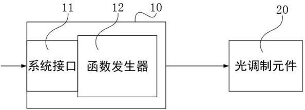
The invention provides a spatial light modulation device, a spatial light modulation method and an optical switch, and relates to the technical field of optical communication. The resource occupationof image signal transmission and the calculation amount of image processing can be reduced and the signal transmission speed can be improved on the basis of realizing the existing spatial light modulation function. The spatial light modulation device comprises an information data generation module, the information data generation module comprises a function generator connected with a system interface, and function operation is carried out on data information input by the system interface to obtain adjustment information with image data. The spatial light modulation device further comprises a light modulation element, the light modulation element comprises a plurality of pixel electrodes arranged in a matrix and a driving circuit, and the driving circuit configures each pixel electrode according to the adjustment information so as to output modulated signal light.

Description

technical field [0001] The present application relates to the technical field of optical communication, and in particular to a spatial light modulation device, a spatial light modulation method, and an optical switch. Background technique [0002] Optical Communication (Optical Communication) is a communication method that uses light waves as the carrier. A dynamic optical network requires equipment to provide wavelength-based configurable functions. Reconfigurable Optical Add-Drop Multiplexing (ROADM) is characterized by the ability to assign wavelengths through software to implement service and wavelength scheduling. ROADM equipment can realize the connection between any two points through software configuration and automatic power balance. [0003] WSS (Wavelength Selective Switch, wavelength selective switch) is used as an optical switch device. The light modulation element in the WSS device, for example, can use a reflective liquid crystal element such as LCoS (Liquid...

Claims


Application Information

Patent Timeline
Patent Type & Authority Patents(China)
IPC IPC(8): H04J14/02H04B10/516G02F1/133G02F1/1343
CPCG02F1/13306G02F1/134309H04B10/516H04J14/0212
Inventor 陈弈星
Owner 南京芯视元电子有限公司
Why Eureka
Try Eureka