Method, system, equipment and storage medium for measuring shear stiffness of segment joints
A technology of segment joint and stiffness, applied in the field of measurement, can solve the problems of high measurement cost and many measurement consumables, and achieve the effect of high measurement accuracy
- Summary
- Abstract
- Description
- Claims
- Application Information
AI Technical Summary
Problems solved by technology
Method used
Image
Examples
Embodiment 1
[0028] In the following description, specific details such as specific system structures and technologies are presented for the purpose of illustration rather than limitation, so as to thoroughly understand the embodiments of the present application. It will be apparent, however, to one skilled in the art that the present application may be practiced in other embodiments without these specific details. In other instances, detailed descriptions of well-known systems, systems, circuits, and methods are omitted so as not to obscure the description of the present application with unnecessary detail.
[0029] It should be understood that when used in this specification and the appended claims, the term "comprising" indicates the presence of described features, integers, steps, operations, elements and / or components, but does not exclude one or more other Presence or addition of features, wholes, steps, operations, elements, components and / or collections thereof.
[0030] It should...
Embodiment 2
[0113] Figure 8 A schematic structural diagram of a shear stiffness measurement system for a segment joint provided in Embodiment 2 of the present invention is shown. For convenience of description, only parts related to the embodiment of the present invention are shown. In the embodiment of the present invention, the segment joint shear stiffness measurement system includes:
[0114] The calibration unit 81 is configured to use two cameras to photograph calibration points on the tube to be measured, obtain pixel coordinates and three-dimensional coordinates of the calibration points, and calibrate the cameras respectively to obtain calibration parameters corresponding to the cameras;
[0115] The three-dimensional coordinate calculation unit 82, the segment to be measured generates an offset amount under the continuous action of the shear force, obtains the starting point image and the end point image of the monitoring point at the joint of the segment to be measured through...
Embodiment 3
[0128] Figure 9 It is a schematic structural diagram of an electronic device provided by an embodiment of the present application. Such as Figure 9 As shown, the electronic device 9 of this embodiment includes: at least one processor 90 ( Figure 9 Only one processor is shown in ), a memory 91, and a computer program 92 stored in the memory 91 and operable on the at least one processor 90, when the processor 90 executes the computer program 92, the above-mentioned Steps in any of the various method embodiments;
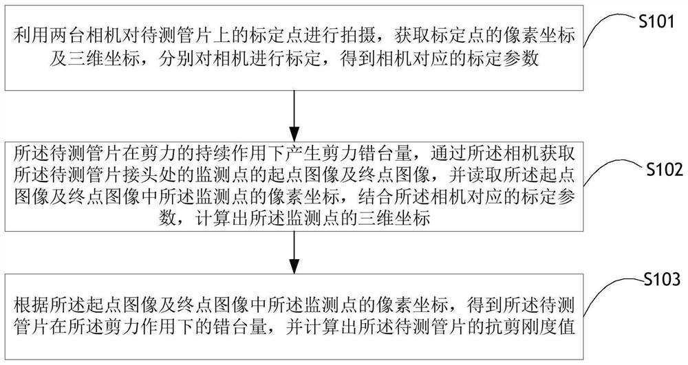
[0129] Utilizing two cameras to photograph calibration points on the tube to be measured, obtaining pixel coordinates and three-dimensional coordinates of the calibration points, and respectively calibrating the cameras to obtain calibration parameters corresponding to the cameras;
[0130] Under the continuous action of the shear force, the segment to be tested produces a displacement amount, and the starting point image and the end point image of the monitoring...
PUM
 Abstract
Description
Claims
Application Information
 - R&D
- Intellectual Property
- Life Sciences
- Materials
- Tech Scout
- Unparalleled Data Quality
- Higher Quality Content
- 60% Fewer Hallucinations
Browse by: Latest US Patents, China's latest patents, Technical Efficacy Thesaurus, Application Domain, Technology Topic, Popular Technical Reports.
© 2025 PatSnap. All rights reserved.Legal|Privacy policy|Modern Slavery Act Transparency Statement|Sitemap|About US| Contact US: help@patsnap.com


